
User Manual


9
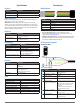
0x17
R/W Name Description Initial Value
R UNIT_ID_LOW Serial number low byte Unique
Bit Function
7:0 Unique serial number of device, high byte.
0x18
R/W Name Description Initial Value
W I2C_ID_HIGH Write serial number high byte for I2C
address unlock
--
Bit Function
7:0 Write the value in UNIT_ID_HIGH (0x16) here as part of enabling a non-
default I2C address. See I2C_ID_LOW (0x19) and I2C_SEC_ADDR (0x1a).
0x19
R/W Name Description Initial Value
W I2C_ID_LOW Write serial number low byte for I2C
address unlock
--
Bit Function
7:0 Write the value in UNIT_ID_LOW (0x17) here as part of enabling a non-default
I2C address. See I2C_ID_HIGH (0x18) and I2C_SEC_ADDR (0x1a).
0x1a
R/W Name Description Initial Value
R/W I2C_SEC_ADDR Write new I2C address after unlock --
Bit Function
7:0 Non-default I2C address.
Available addresses are 7-bit values with a ‘0’ in the least signicant bit (even
hexadecimal numbers).
I2C_ID_HIGH (0x18) and I2C_ID_LOW (0x19) must have the correct value for
the device to respond to the non-default I2C address.
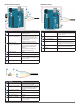
0x1c
R/W Name Description Initial Value
R/W THRESHOLD_
BYPASS
Peak detection threshold bypass 0x00
Bit Function
7:0 0x00: Use default valid measurement detection algorithm based on the peak
value, signal strength, and noise in the correlation record.
0x01-0xff: Set simple threshold for valid measurement detection. Values 0x20-
0x60 generally perform well.
0x1e
R/W Name Description Initial Value
R/W I2C_CONFIG Default address response control 0x00
Bit Function
5 0: Disables the alternate status mode.
1: Enables an alternate indication status byte at STATUS register 0x01.
NOTE: If bit 5 is enabled (1), the status word consists of all ones except for
the bit position selected by bits [2:0] in this I2C CONFIG register (0x1e). This
allows for the reading of the busy status of multiple units sharing the same
active base address 0x62.
4 0: Disables the altrenative I2C address.
1: Enables the alternative I2C address.
3 0: Device will respond to I2C address 0x62. Device will also respond to
non-default address if congured successfully. See I2C_ID_HIGH (0x18),
I2C_ID_LOW (0x19), and I2C_SEC_ADDR (0x1a).
1: Device will only respond to non-default I2C address. It is recommended to
congure the non-default address rst, then use the non-default address to
write to this register, ensuring success.
2:0 Denes the bit position(s) to remain set as 0 when bit 5 is enabled.
0x26
R/W Name Description Initial Value
R/W PEAK STACK
HIGH BYTE
Registers read successive values
from the peak stack register. Data
from the stack register is used for post
processing.
--
Bit Function
10:8 For every 11-bit stack value, this resister (0x26) must be read rst. Reading
from this register latches the low order data into 0x27 and increments the
stack pointer.
Writing 0x01 to this register (0x26) resets the stack pointer to the rst element.
0x27
R/W Name Description Initial Value
R/W PEAK STACK
LOW BYTE
Registers read successive values
from the peak stack register. Data
from the stack register is used for post
processing.
--
Bit Function
7:0 Reading from 0x27 reads the low order data from this register.
0x40
R/W Name Description Initial Value
R/W TEST COMMAND State command --
Bit Function
2:0 000: Test mode disable, resume normal operation
111: Test mode enable, allows download of correlation record
Once test mode is enabled, read CORR_DATA (0x52) and CORR_DATA_
SIGN (0x53) in one transaction (read from 0xd2). The memory index is
incremented automatically and successive reads produce sequential data.