
User Manual


8
Detailed Control Register Denitions
NOTE: Unless otherwise noted, all registers contain one byte and are read
and write.
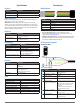
0x00
R/W Name Description Initial Value
W ACQ_COMMAND Device command --
Bit Function
7:1 Write any non-zero value to start a measurement
0 Performs a hard reset by reloading the FPGA and returning all registers to
default values
This operation must be enabled by writing 1 to bit 0 on register 0x06.
When reset the I2C lines go into a high-z state for up to 10 ms. This has the
potential to cause legacy-microcontroller-interface code to crash.
0x01
R/W Name Description Initial Value
R STATUS System status --
Bit Function
5 Health Flag
0: Error detected
1: Reference and receiver bias are operational
4 Device command regulation ag
0: device is not in DC regulation
1: device is in DC regulation
3 Peak detection ag
0: No signal detected
1: Peak detected
2 Reference Overow Flag
0: Reference data has not overowed
1: Reference data in correlation record has reached the maximum value
before overow (occurs periodically)
1 Signal Overow Flag
0: Signal data has not overowed
1: Signal data in correlation record has reached the maximum value before
overow (occurs with a strong received signal strength)
Additional returns can be evaluated using data downloaded from the peak
stack registers, 0x26 and 0x27 (page 9).
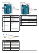
0x02
R/W Name Description Initial Value
R/W SIG_COUNT_VAL Maximum acquisition count 0xFF
Bit Function
7:0 Maximum number of acquisitions during measurement
0x04
R/W Name Description Initial Value
R/W ACQ_CONFIG_REG Acquisition mode control 0x08
Bit Function
7 0: Record download resolution set at 9 bits (legacy)
1: Record download resolution set at 12 bits
6 0: Enable reference process during measurement
1: Disable reference process during measurement
5 0: DC compensation enabled
1: DC compensation disabled
4 0: Enable reference lter, averages multiple reference measurements for
increased consistency
1: Disable reference lter
3 0: Enable measurement quick termination. Device will terminate distance
measurement early if it anticipates that the signal peak in the correlation
record will reach maximum value.
1: Disable measurement quick termination.
2 bit unused
1:0 Mode Select Pin Function Control
00: Default PWM mode. Pull pin low to trigger measurement, device will
respond with an active high output with a duration of 10us/cm.
01: Status output mode. Device will drive pin active high while busy. Can be
used to interrupt host device.
10: Fixed delay PWM mode. Pulling pin low will not trigger a measurement.
11: Oscillator output mode. Nominal 31.25 kHz output. The accuracy of the
silicon oscillator in the device is generally within 1% of nominal. This affects
distance measurements proportionally and can be measured to apply a
compensation factor.
0x06
R/W Name Description Initial Value
R LEGACY_RESET_EN Enables legacy unit reset --
Bit Function
0 Writing 1 to bit 0 enables the legacy reset operation using the 0x00 register.
0x0e
R/W Name Description Initial Value
R SIGNAL_STRENGTH Received signal strength --
Bit Function
7:0 Received signal strength calculated from the value of the highest peak in the
correlation record and how many acquisitions were performed.
0x0f
R/W Name Description Initial Value
R FULL_DELAY_HIGH Distance measurement high byte --
Bit Function
7:0 Distance measurement result in centimeters, high byte.
0x10
R/W Name Description Initial Value
R FULL_DELAY_LOW Distance measurement low byte --
Bit Function
7:0 Distance measurement result in centimeters, low byte.
0x12
R/W Name Description Initial Value
R/W REF_COUNT_VAL Reference acquisition count 0x03
Bit Function
7:0 Non-default number of reference acquisitions during measurement. ACQ_
CONFIG_REG (0x04) bit 2 must be set.
0x16
R/W Name Description Initial Value
R UNIT_ID_HIGH Serial number high byte Unique
Bit Function
7:0 Unique serial number of device, high byte.