
User Manual


7
I2C Protocol Operation
This protocol description uses the term master to refer to the Arduino
controller, and uses the term LIDAR device to refer to the LIDAR-Lite v3HP
device acting as a slave on the I2C bus.
When working with the I2C serial bus protocol, the device operates as follows:
1
The master initiates data transfer by establishing a start condition, which
consists of a high-to-low transition on the SDA line while SCL is high.
2
The master sends an address byte, which consists of the 7-bit slave
address.
3
The master sends a read/write bit with a zero state indicating a write
request.
A write operation is used as the initial stage of both read and write
transfers.
4
If the slave address corresponds to the LIDAR device address, the LIDAR
device responds by pulling SDA low during the ninth clock pulse.
This operation is considered the acknowledge bit.
At this stage, all other devices on the bus remain idle while the selected
LIDAR device waits for data to be written to or read from its shift register.
5
Data transmits over the serial bus in sequences of nine clock pulses (eight
data bits followed by an acknowledge bit).
These transmissions must occur on the SDA line during the low period of
SCL and remain stable during the high period of SCL.
6
The master sends an 8-bit data byte following the slave address, which
loads the I2C control register on the LIDAR device with the address of the
rst control register to be accessed.
Note: If the high bit (Bit 7) is set, it enables automatic incrementing for
successive reads/writes.
7
The master requests a read operation from the LIDAR device or sends a
write operation to the LIDAR device.
Read Operation
After the master establishes communication with the LIDAR device, obtaining
a reading from the LIDAR device operates as follows.
1
The rst data frame sets the address of the desired read register. The
master sends a stop bit at the completion of the rst data frame.
2
The master initiates a new start condition, which consists of the slave
address with the read bit set (one state).
3
The master reads one or more data bytes in succession.
A
The LIDAR device sends an acknowledge bit to the master when it
receives a valid address.
B
The master releases the SDA data line with continued clocking of the
SCL line.
C
The master strobes the acknowledge bit and continues the read cycle.
4
After the read cycle is done, the master sends a stop condition to complete
the operation.
Write Operation
After the master establishes communication with the LIDAR device, writing to
the LIDAR device operates as follows.
1
The master sends one or more 8-bit data blocks to the LIDAR device.
A
The LIDAR device sends an acknowledge bit to the master when it
receives and writes a valid data byte.
B
The master releases the SDA data line with continued clocking of the
SCL line.
C
The master strobes the acknowledge bit and continues the write cycle,
if necessary.
3
After the write cycle is done, the master sends a stop condition to complete
the operation.
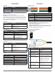
Register Denitions
Control Register List
Address R/W Name Description Intial Value Details
0x00 W ACQ_COMMAND Device command -- page 8
0x01 R STATUS System status -- page 8
0x02 R/W SIG_COUNT_VAL Maximum acquisition count 0xFF page 8
0x04 R/W ACQ_CONFIG_REG Acquisition mode control 0x08 page 8
0x06 W LEGACY_RESET_EN Enables unit reset -- page 8
0x0e R SIGNAL_STRENGTH Received signal strength -- page 8
0x0f R FULL_DELAY_HIGH Distance measurement high byte -- page 8
0x10 R FULL_DELAY_LOW Distance measurement low byte -- page 8
0x12 R/W REF_COUNT_VAL Reference acquisition count 0x03 page 8
0x16 R UNIT_ID_HIGH Serial number high byte Unique page 8
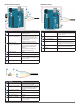
0x17 R UNIT_ID_LOW Serial number low byte Unique page 9
0x18 W I2C_ID_HIGH Write serial number high byte for I2C address unlock -- page 9
0x19 W I2C_ID_LOW Write serial number low byte for I2C address unlock -- page 9
0x1a R/W I2C_SEC_ADDR Write new I2C address after unlock -- page 9
0x1c R/W THRESHOLD_BYPASS Peak detection threshold bypass 0x00 page 9
0x1e R/W I2C_CONFIG Default address response control 0x00 page 9
0x26 R/W PEAK STACK HIGH BYTE Used for post processing of correlation peak data -- page 9
0x27 R/W PEAK STACK LOW BYTE Used for post processing of correlation peak data -- page 9
0x40 R/W COMMAND State command -- page 9
0x48 R HEALTH STATUS Used to diagnose major hardware issues at initialization -- page 10
0x52 R CORR_DATA Correlation record data low byte -- page 10
0x53 R CORR_DATA_SIGN Correlation record data high byte -- page 10
0x65 R/W POWER_CONTROL Power state control 0 page 10