
User Manual


5
frequent erroneous measurements, and 0x60 for reduced sensitivity and fewer
erroneous measurements.
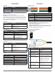
Congurable I2C Address
Address Name Description Initial Value
0x16 UNIT_ID_HIGH Serial number high byte Unique
0x17 UNIT_ID_LOW Serial number low byte Unique
0x18 I2C_ID_HIGH Write serial number high byte for
I2C address unlock
--
0x19 I2C_ID_LOW Write serial number low byte for
I2C address unlock
--
0x1a I2C_SEC_ADDR Write new I2C address after
unlock
--
0x1e I2C_CONFIG Default address response
control
0x00
The I2C address can be changed from its default value. Available addresses
are 7-bit values with a ‘0’ in the least signicant bit (even hexadecimal
numbers).
To change the I2C address, the unique serial number of the unit must be read
then written back to the device before setting the new address. The process is
as follows:
1
Read the two byte serial number from 0x96 (high byte 0x16 and low byte
0x17).
2
Write the serial number high byte to 0x18.
3
Write the serial number low byte to 0x19.
4
Write the desired new I2C address to 0x1a.
5
Write 0x08 to 0x1e to disable the default address.
This can be used to run multiple devices on a single bus, by enabling one,
changing its address, then enabling the next device and repeating the
process.
The I2C address will be restored to default after a power cycle.
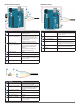
Power Control
Address Name Description Initial Value
0x65 POWER_CONTROL Power state control 0
Setting bit 1 in this register disables the receiver circuit, saving roughly
40 mA. After being re-enabled, the receiver circuit stabilizes by the time a
measurement can be performed.
NOTE: The most effective way to control power usage is to utilize the enable
pin to deactivate the device when not in use.