
User Manual


3
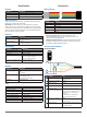
Standard Arduino I2C Wiring
➋
➏
➌
➊
➐
➍
➎
Item Description Notes
➊
680µF electrolytic capacitor You must observe the correct polarity when
installing the capacitor.
➋
Pull-up resistor connection
(not required in all applications)
In installations with long cable extensions
or with multiple devices on the I2C bus, you
must connect the pull-up resistors on the
SDA and SCL wires to the logic rail on your
microcontroller board.
On an Arduino board, this is the 5v pin.
➌
4.7kΩ pull-up resistor
(not required in all applications)
In installations with long cable extensions
or with multiple devices on the I2C bus, you
must install a 1kΩ to 10kΩ pull-up resistor
on each I2C wire to account for cable
capacitance.
It is recommended to start with 4.7kΩ
resistors and adjust if necessary.
➍
I2C SDA connection Blue wire
➎
I2C SCL connection Green wire
➏
5 Vdc power (+) connection Red wire
The sensor operates at 4.75 through 5.5 Vdc,
with a max. of 6 Vdc.
➐
Power ground (-) connection Black wire
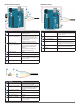
PWM Wiring
➋
➏
➌
➊
➎
➍
Item Description Notes
➊
Trigger pin on microcontroller Connect the other side of the resistor to the
trigger pin on your microcontroller.
➋
Monitor pin on microcontroller Connect one side of the resistor to the mode-
control connection on the device, and to a
monitoring pin on your microcontroller.
➌
Power ground (-) connection Black Wire
➍
1kΩ resistor
➎
Mode-control connection Yellow wire
➏
5 Vdc power (+) connection Red wire
The sensor operates at 4.75 through 5.5 Vdc,
with a max. of 6 Vdc.
PWM Arduino Wiring
➋
➎
➌
➊
➍
➏
Item Description Notes
➊
5 Vdc power (+) connection Red wire
The sensor operates at 4.75 through 5.5 Vdc,
with a max. of 6 Vdc.
➋
Power ground (-) connection Black Wire
➌
Mode-control connection Yellow wire
➍
Monitor pin on microcontroller Connect one side of the resistor to the mode-
control connection on the device, and to a
monitoring pin on your microcontroller board.
➎
Trigger pin on microcontroller Connect the other side of the resistor to the
trigger pin on your microcontroller board.
➏
1kΩ resistor