
User Manual


2
Specications
Physical
Specication Measurement
Size (LxWxH) 20 × 48 × 40 mm (0.8 × 1.9 × 1.6 in.)
Weight 22 g (0.78 oz.)
Operating temperature -20 to 60°C (-4 to 140°F)
Water Resistance
Body of this device is rated IPX7, and can wthstand incidental exposure to
water of up to 1 meter for up to 30 minutes.
IMPORTANT: The bare wire portion of the wiring harness is not water
resistant, and can act as a path for water to enter the device. All bare-wire
connections must either be made in a water-tight location or properly sealed.
Water may enter under the transmitting lens. This could affect performance,
but will not affect IPX7 water resistance.
Electrical
Specication Measurement
Power 5 Vdc nominal
4.5 Vdc min., 5.5 Vdc max.
Current consumption 65 mA idle
85 mA during an acquisition
Performance
Specication Measurement
Range (70% reective target) 40 m (131 ft)
Resolution +/- 1 cm (0.4 in.)
Accuracy < 2 m ±5 cm (2 in.) typical*
Accuracy ≥ 2 m ±2.5 cm (1 in.) typical
Mean ±1% of distance maximum
Ripple ±1% of distance maximum
Update rate (70% Reective Target) Greater than 1 kHz typical
Reduced sensitivity at high update rates
*Nonlinearity present below 1 m (39.4 in.)
Interface
Specication Measurement
User interface I2C
PWM
External trigger
I2C interface Fast-mode (400 kbit/s)
Default 7-bit address 0x62
Internal register access & control
PWM interface External trigger input
PWM output proportional to distance at 10 μs/cm
Laser
Specication Measurement
Wavelength 905 nm (nominal)
Total laser power (peak) 1.3 W
Mode of operation Pulsed (256 pulse max. pulse train)
Pulse width 0.5 μs (50% duty cycle)
Pulse train repetition frequency 10-20 kHz nominal
Energy per pulse <280 nJ
Beam diameter at laser aperture 12 × 2 mm (0.47 × 0.08 in.)
Divergence 8 mRad
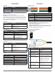
Connections
Wiring Harness
Wire Color Function
Red 5 Vdc (+)
Orange Power enable (internal pull-up)
Yellow Mode control
Green I2C SCL
Blue I2C SDA
Black Ground (-)
There are two basic congurations for this device:
• I2C (Inter-Integrated Circuit)—a serial computer bus used to
communicate between this device and a microcontroller, such as an
Arduino board (I2C Interface, page 4).
• PWM (Pulse Width Modulation)—a bi-directional signal transfer method
that triggers acquisitions and returns distance measurements using the
mode-control pin (Mode Control Pin, page 4).
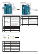
I2C Connection Diagrams
Standard I2C Wiring
➋
➎
➌
➊
➍
➏
➐
Item Description Notes
➊
680µF electrolytic capacitor You must observe the correct polarity when
installing the capacitor.
➋
Power ground (-) connection Black wire
➌
I2C SDA connection Blue wire
➍
I2C SCL connection Green wire
➎
4.7kΩ pull-up resistor
(not required in all applications)
In installations with long cable extensions
or with multiple devices on the I2C bus, you
must install a 1kΩ to 10kΩ pull-up resistor
on each I2C wire to account for cable
capacitance.
It is recommended to start with 4.7kΩ
resistors and adjust if necessary.
➏
5 Vdc power (+) connection Red wire
The sensor operates at 4.75 through 5.5 Vdc,
with a max. of 6 Vdc.
➐
Logic rail connection The pull-up resistors connected to both I2C
wires must connect to the logic rail on your
microcontroller board.