
User Manual


10
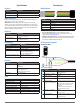
0x48
R/W Name Description Initial Value
R HEALTH STATUS Used to diagnose major hardware issues
at system initialization.
--
Bit Function
4:0 Reference value is within normal range.
3 Reference overow occurred during the rst acquisition.
2 An initial acquisition was completed at wake-up to set the initial reference
value.
1 The receiver DC control command is within the normal range.
0 DC regulation was successful during wake-up.
0x52
R/W Name Description Initial Value
R CORR_DATA Correlation record data low byte --
Bit Function
7:0 Correlation record data low byte. See CORR_DATA_SIGN (0x53), ACQ_
SETTINGS (0x5d), and COMMAND (0x40).
0x53
R/W Name Description Initial Value
R CORR_DATA_SIGN Correlation record data high byte --
Bit Function
7:0 Correlation record data high byte. Correlation record data is a 2’s complement
9-bit value, and must be sign extended to be formatted as a 16-bit 2’s
complement value. Thus when repacking the two bytes obtained for the I2C
transaction, set the high byte to 0xff if the LSB of the high byte is one.
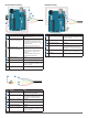
0x65
R/W Name Description Initial Value
R/W POWER_CONTROL Power state control 0x80
Bit Function
0 1: Disable receiver circuit
0: Enable receiver circuit. Receiver circuit stabilizes by the time a
measurement can be performed.
Frequently Asked Questions
How do I use the device for fast-scanning
applications?
Using the LIDAR-Lite v3HP device for fast-scanning applications may
require you to change the program you used for “continuous” or “burst” mode
functions with previous versions of the sensor.
1
Initiate new measurement command.
2
Immediately read the distance registers, obtaining the previous
measurement results while the new measurement is occurring.
Measurement data stored in the sensor is valid until a new measurement
concludes.
3
Perform other actions while polling the status bit until it indicates an idle
state.
4
Repeat steps 1 through 3.
NOTES:
• This method uses slightly more I2C overhead, but it allows more efcient
polling if you know about your measurement time, which depends on
maximum acquisition count settings. You also know exactly when that
measurement begins.
• With this approach (and nothing else going on except relentless polling),
the device has been able to reach >1.5 kHz with very small acquisition
count settings.
• You can nd sample Arduinio code for this in the Garmin GitHub
repository at the following location: https://github.com/garmin/LIDARLite_
v3_Arduino_Library/blob/master/examples/ShortRangeHighSpeed/
ShortRangeHighSpeed.ino.
Does the device operate only on 5 Vdc?
The device requires 5 Vdc to function properly.
NOTICE
Connecting the device to a source greater or less than 5 Vdc is not supported,
and may result in poor performance or may damage the device.
What is the spread of the laser beam?
At very close distances (less than 1 m), the beam diameter is about the size
of the aperture (lens). For distances greater than 1 m, you can estimate the
beam diameter using this equation:
Distance/100 = beam diameter at that distance (in whatever units you
measured the distance).
The actual spread is ~8 milli radians or ~1/2 degree.
How do distance, target size, aspect, and reectivity
affect returned signal strength?
The device transmits a focused infrared beam that reects off of a target,
and a portion of that reected signal returns to the receiver. The distance is
calculated by taking the difference between the moment of signal transmission
to the moment of signal reception. Successfully receiving a reected signal is
heavily inuenced by several factors. These factors include:
• Target Distance
The relationship of distance (D) to returned signal strength is an inverse
square. With an increase in distance, the returned signal strength
decreases by 1/D^2 or the square root of the distance.
• Target Size
The relationship of a target’s Cross Section (C) to returned signal strength
is an inverse power of four. The device transmits a focused near-infrared
laser beam that spreads at a rate of approximately 0.5º as distance
increases. Up to 1 m, it is approximately the size of the lens. Beyond 1 m,
the approximate beam spread in degrees can be estimated by dividing the
distance by 100, or ~8 milliradians. When the beam overlls (is larger than)
the target, the signal returned decreases by 1/C^4 or the fourth root of the
target’s cross section.