
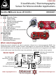
User Manual
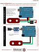
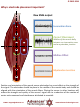


Connecting external electrode cables
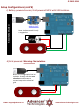
Ref
End
Middle
EMAIL: support@advancer.co
www.AdvancerTechnologies.com
© 2015-2016
This new version has embedded electrode
snaps right on the sensor board itself,
replacing the need for a cable. However, if
the on board snaps do not fit a user’s
specific application, an external cable can
be connected to the board through three
through hole pads shown above.
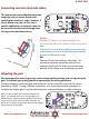
Middle
Connect this pad to the cable leading to an
electrode placed in the middle of the muscle body.
End
Connect this to the cable leading to an electrode
placed adjacent to the middle electrode towards
the end of the muscle body.
Ref
Connect this to the reference electrode. The
reference electrode should be placed on an
separate section of the body, such as the bony
portion of the elbow or a nonadjacent muscle
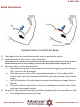
Adjusting the gain
We recommend for users to get their sensor setup working reliably prior to adjusting the
gain. The default gain setting should be appropriate for most applications.
To adjust the gain, locate the gain potentiometer in the lower left corner of the sensor
(marked as “GAIN”). Using a Phillips screwdriver, turn the potentiometer clockwise to
increase the output gain; turn the potentiometer counterclockwise to reduce the gain.
Note: In order to reduce the required voltage for the
sensor, the redesign switch out a JFET amplifier for a
CMOS amplifier. However CMOS amplifiers tend to have
slower recovery times when saturated. Therefore, we
advise users to adjust the gain such that the output signal
will not saturate the amplifier.