
User Manual


HMC6343
www.honeywell.com 7
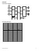
Mounting Orientations
The HMC6343 provides for three standard mounting orientations, with a flat horizontal orientation (Level) as the factory
default. For vertical mounting, there are two upright orientations with either the X-axis or the Z-axis designated as the
forward reference directions. To change the forward reference direction temporarily, send the appropriate command byte
(0x72, 0x73, or 0x74) for level or upright orientations. For other orientations, you can add or subtract 90 degree
increments of deviation angle as required from the three choices. The figure below shows pictorially the orientations.
To permanently change orientation, poke EEPROM Operational Mode Register 1 (0x04) with the appropriate binary bits
set for Level, Upright Edge (UE), or Upright Front (UF). The HMC6343 will operate in the selected orientation after a
power-up or reset command. More on the EEPROM registers in the following sections.
I
2
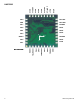
C COMMUNICATION PROTOCOL
The HMC6343 communicates via a two-wire I
2
C bus system as a slave device. The HMC6343 uses a layered protocol
with the interface protocol defined by the I
2
C bus specification, and the lower command protocol defined by Honeywell.
The data rate is the standard-mode 100kbps rate as defined in the I
2
C Bus Specification 2.1. The bus bit format is an 8-bit
Data/Address send and a 1-bit acknowledge bit. The format of the data bytes (payload) shall be case sensitive ASCII
characters or binary data to the HMC6343 slave, and binary data returned. Negative binary values will be in two’s
complement form. The default (factory) HMC6343 7-bit slave address is 0x32 for write operations, or 0x33 for read
operations.
The HMC6343 Serial Clock (SCL) and Serial Data (SDA) lines do not have internal pull-up resistors, and require resistive
pull-ups (Rp) between the master device (usually a host microprocessor) and the HMC6343. Pull-up resistance values of
about 10k ohms are recommended with a nominal 3.3-volt supply voltage. Other values may be used as defined in the I
2
C
Bus Specification 2.1.
The SCL and SDA lines in this bus specification can be connected to a host of devices. The bus can be a single master to
multiple slaves, or it can be a multiple master configuration. All data transfers are initiated by the master device which is
responsible for generating the clock signal, and the data transfers are 8 bit long. All devices are addressed by I
2
C’s
unique 7 bit address. After each 8-bit transfer, the master device generates a 9
th
clock pulse, and releases the SDA line.
HONEYWELL
HMC6343
0626
x
YZ
LEVEL
Y
X
Z
UPRIGHT EDGE
Y
UPRIGHT FRONT
X
Z
0x72
0x73
0x74
HMC6343 ORIENTATIONS
Red Arrow is the Forward Direction
HONEYWELL
HMC6343
0626
x
YZ
LEVEL
Y
X
Z
UPRIGHT EDGE
Y
UPRIGHT FRONT
X
Z
0x72
0x73
0x74
HMC6343 ORIENTATIONS
Red Arrow is the Forward Direction