
User Manual


HMC6343
12
www.honeywell.com
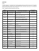
Operational Mode Registers
EEPROM registers 0x04 and 0x05 contain bits that are read for operational mode status and for setting the Run Mode
measurement rate. The tables below describe the register contents and interpretation. It is recommended that Operational
Mode Register 1 and 2 written only to change default orientation and update measurement rate.
Table 4 – Operational Mode Register 1 (EEPROM 0x04)
OM1_7 OM1_6 OM1_5 OM1_4 OM1_3 OM1_2 OM1_1 OM1_0
Comp(0) Cal(0) Filter(0) Run(1) Stdby(0) UF(0) UE(0) Level(1)
Table 5 – Operational Mode Register 1 Bit Designations
Location Name Description
OM1_7 Comp Calculating compass data if set. (read only)
OM1_6 Cal Calculating calibration offsets if set. (read only)
OM1_5 Filter IIR Heading Filter used if set.
OM1_4 Run Run Mode if set.
OM1_3 Stdby Standby Mode if set.
OM1_2 UF Upright Front Orientation if set.
OM1_1 UE Upright Edge Orientation if set.
OM1_0 Level Level Orientation if set
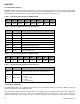
Table 6 – Operational Mode Register 2 (EEPROM 0x05)
OM2_7 OM2_6 OM2_5 OM2_4 OM2_3 OM2_2 OM2_1 OM2_0
(0) (0) (0) (0) (0) (0) MR1(0) MR0(1)
Table 7 – Operational Mode Register 2 Bit Designations
Location Name Description
OM2_7 to
OM2_2
0 These bits must be cleared for correct operation.
OM2_1 to
OM2_0
MR1, MR0
Measurement Rate
0,0 = 1Hz
0,1 = 5Hz (default)
1,0 = 10Hz
1,1 = Not Assigned
User Hard-Iron Calibration
The HMC6343 provides a user calibration routine with the 0x71 command permitting entry into the calibration mode and
the 0x7E command to exit the calibration mode.
After entering the calibration mode, rotate the device reasonably steady for 360 degrees about the Y (Left - Right) axis
and then 360 degrees about Z (Up - Down) axis. During the first rotation, maintain the Y axis at Level as much as
possible. Maintain the Z axis upright as much as possible during the second rotation and until the exit calibration