
User Manual


HMC6343
www.honeywell.com 11
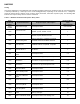
Timing
Upon power application to the HMC6343, wait nominally 500 milli-seconds before sending the first I2C command (typically
a 0x32 byte followed by a 0x50 byte for the usual heading/pitch/roll). Depending on the command sent, a delay time
should be inserted before clocking out the response bytes (send 0x33, clock back response bytes). The following table
indicates the response delay times for various commands.
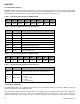
Table 3 – HMC6343 Command to Response Delay Times
Prior
Command
(hex)
Commanded Action Response Bytes & Description
Res
ponse/Delay
Time
(milli-seconds)
Power
Applied
VDD1-3 low to high No Response Data 500 nominally
0x40
Post Accel Data.
6 binary data Bytes. AxMSB, AxLSB,
AyMSB, AyLSB, AzMSB, AzLSB
1
0x45
Post Mag Data.
6 binary data Bytes.
MxMSB, MxLSB,
MyMSB, MyLSB, MzMSB, MzLSB
1
0x50 Post Heading Data.
6 binary data Bytes. HeadMSB, HeadLSB,
PitchMSB, PitchLSB, RollMSB, RollLSB
1
0x55
Post Tilt Data.
6 binary data Bytes. PitchMSB, PitchLSB,
RollMSB, RollLSB, TempMSB, TempLSB
1
0x65 Post OP Mode 1 OP Mode 1 1
0x71
Enter User Calibration
Mode
No Response Data 0.3
0x72 Level Orientation (X=forward, +Z=up) (default) No Response Data 0.3
0x73
Upright Sideways
Orientation
(X=forward, Y=up) No Response Data 0.3
0x74
Upright Flat Front
Orientation
(Z=forward, -X=up) No Response Data 0.3
0x75 Enter Run Mode No Response Data 0.3
0x76 Enter Standby Mode No Response Data 0.3
0x7E
Exit User Calibration
Mode
No Response Data 50
0x82 Reset the Processor No Response Data 500
0x83 Enter Sleep Mode No Response Data 1
0x84 Exit Sleep Mode No Response Data 20
0xE1
Read from EEPROM,
RAM
1 binary data Byte 10
0xF1 Write to EEPROM, RAM No Response Data. Data Settling Time 10