
User Manual

LDT with Crimps Vibration Sensor/Switch
LDT0-028K Piezo Vibration Rev 1 www.meas-spec.com 10/13/2008
2 of 4
examples of properties
Four differen
t experiments serve to illustrate the various properties of this
simple but versatile component.
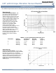
Experiment #1
LDT0 as Vibration Sensor
- with
the crimped contacts pushed through a
printed-circuit board, the LDT0 was
soldered carefully in place to anchor the
sensor. A charge amplifier was used to
detect the output signal as vibration from
a shaker table was applied (using a
charge amplifier allows a very long
measurement time constant and thus
allows the "open-circuit" voltage
response to be calculated). Small
masses (approximately 0.26g
increments) were then added to the tip of
the sensor, and the measurement
repeated. Results are shown in Table 1
and the overlaid plots in Fig. 1. Without
adding mass, the LDT0 shows a
resonance around 180 Hz. Adding mass
to the tip reduces the resonance
frequency and increases "baseline"
sensitivity.
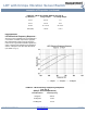
TABLE
1
:
LDT0 as Vibration Sensor
(see Fig 1)
Added Mass Baseline
Sensitivity
Sensitivity at
Resonance
Resonant
Frequency
+3 Db
Frequency
0 50 mV/g 1.4 V/g 180 Hz 90 Hz
1
200 mV/g 4 V/g 90 Hz 45 Hz
2
400 mV/g 8 V/g 60 Hz 30 Hz
3
800 mV/g 16 V/g 40 Hz 20 Hz
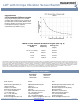
Experiment #2
LDT0 as Flexible Switch
- using a charge
amplifier to obtain "open-circuit" voltage sensitivity,
the output was measured for controlled tip
deflections applied to the sensor (supported by its
crimped contacts as described above). 2 mm
deflection was sufficient to generate about 7 V.
Voltages above 70V could be generated by
bending the tip of the sensor through 90° (see
Table 2, Fig. 2).