
User Manual
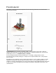
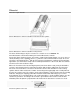

Size scaled 10k and 100k pots that combine traditional mountings and knob shafts with newer and smaller
electrical assemblies. Note the "B" designating a linear taper.
The relationship between slider position and resistance, known as the "taper" or "law", is controlled
by the manufacturer. In principle any relationship is possible, but for most
purposes linear or logarithmic (aka "audio taper") potentiometers are sufficient.
A letter code may be used to identify which taper is used, but the letter code definitions are not
standardized. Newer potentiometers will usually be marked with an 'A' for logarithmic taper or a 'B'
for linear taper. Older potentiometers may be marked with an 'A' for linear taper, a 'C' for logarithmic
taper or an 'F' for anti-logarithmic taper. The code used also varies between different manufacturers.
When a percentage is referenced with a non-linear taper, it relates to the resistance value at the
midpoint of the shaft rotation. A 10% log taper would therefore measure 10% of the total resistance
at the midpoint of the rotation; i.e. 10% log taper on a 10K ohm potentiometer would yield 1K at the
midpoint. The higher the percentage the steeper the log curve
[2]
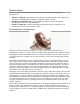
Linear taper potentiometer
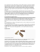
A linear taper potentiometer (linear describes the electrical characteristic of the device, not the
geometry of the resistive element) has a resistive element of constant cross-section, resulting in a
device where the resistance between the contact (wiper) and one end terminal is proportional to the
distance between them. Linear taper potentiometers
[3]
are used when the division ratio of the
potentiometer must be proportional to the angle of shaft rotation (or slider position), for example,
controls used for adjusting the centering of the display on an analog cathode-ray oscilloscope.
Precision potentiometers have an accurate relationship between resistance and slider position.
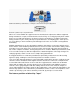
Logarithmic potentiometer
A logarithmic taper potentiometer has a resistive element that either 'tapers' in from one end to the
other, or is made from a material whose resistivity varies from one end to the other. This results in a
device where output voltage is a logarithmic function of the slider position.
[4]
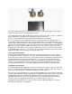
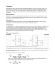
Most (cheaper) "log" potentiometers are not accurately logarithmic, but use two regions of different
resistance (but constant resistivity) to approximate a logarithmic law. The two resistive tracks overlap
at approximately 50% of the potentiometer rotation; this gives a stepwise logarithmic taper.
[5]
A
logarithmic potentiometer can also be simulated (not very accurately) with a linear one and an
external resistor. True logarithmic potentiometers are significantly more expensive.
Logarithmic taper potentiometers are often used in connection with audio amplifiers as human
perception of audio volume is logarithmic.