
Data Sheet


E6A2-C
3
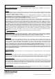
I/O Circuit Diagrams
Safety Precautions
Refer to Warranty and Limitations of Liability.
This product is not designed or rated for ensuring
safety of persons either directly or indirectly.
Do not use it for such purposes.
Do not use the Encoder under ambient conditions that exceed the ratings.
● Wiring
Spurious pulses may be generated when power is turned ON and
OFF. Wait at least 0.1 s after turning ON the power to the Encoder
before using the connected device, and stop using the connected
device at least 0.1 s before turning OFF the power to the Encoder.
Also, turn ON the power to the load only after turning ON the power
to the Encoder.
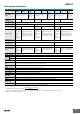
Model/Output Circuits Output mode Connection
E6A2-CS3C
E6A2-CS5C
0 V
E6A2-C@@3C: +5 to 12 V
(
E6A2-C@@5C: +12 to 24V
)
Vcc
E6A2
main
circuit
Brown
Blue
Black, white, orange
30 VDC
30 mA max.
(Black: phase A,
White: phase B,
Orange: phase Z)
Output
ON
OFF
T(100%)
1/2T±1/4T (50%±25%)
Output transistor
The ONs in the above timing chart mean that the
output transistor is ON and the OFFs mean that the
output transistor is OFF.
Note: 1. The white and orange wires
of Single Models (E6A2-
CS@@) do not output
signals (no connection).
2. The white and orange wires
of Single Models (E6A2-
CS@@) do not output
signals (no connection).
3. Voltage Output Models are
capable of sinking a
maximum current of 20 mA.
Color Signal
Brown Vcc
Black Phase A
White Phase B
Orange Phase Z
Blue 0 V (common)
E6A2-CW3C
E6A2-CW5C
E6A2-CWZ3C
E6A2-CWZ5C
0 V
E6A2-C@@3C: +5 to 12 V
(
E6A2-C@@5C: +12 to 24V
)
Vcc
E6A2
main
circuit
Brown
Blue
Black, white, orange
30 VDC
30 mA max.
(Black: phase A,
White: phase B,
Orange: phase Z)
Output
Output transistor
ON
OFF
ON
OFF
ON
OFF
ON
OFF
ON
OFF
ON
OFF
T(360˚)
1/4±1/8T (90˚±45˚)
1/4±1/8T (90˚±45˚)
T(360˚)
Phase A
Phase B
Phase Z
Phase A
Phase B
Phase Z
CW
CCW
Direction of rotation: CW
(as viewed from end of shaft)
Direction of rotation: CCW
(as viewed from end of shaft)
Note: Phase A is 1/4 T ± 1/8 T
faster than phase B.
Note: Phase A is 1/4 T ± 1/8 T
slower than phase B.
The ONs in the above timing chart mean that the
output transistor is ON and the OFFs mean that the
output transistor is OFF.
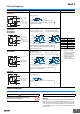
E6A2-CW3E
E6A2-CWZ3E
0 V
2 kΩ
Vcc (+5 to 12 V)
E6A2
main
circuit
Brown
Blue
20 mA
max.
Black, white, orange
Output (Black: phase A,
White: phase B,
Orange: phase Z)
Output transistor
Direction of rotation: CW
(as viewed from end of shaft)
Direction of rotation: CCW
(as viewed from end of shaft)
Note: Phase A is 1/4 T ± 1/8 T
faster than phase B.
Note: Phase A is 1/4 T ± 1/8 T
slower than phase B.
H
L
H
L
H
L
H
L
H
L
H
L
T(360˚)
1/4±1/8T(90˚±45˚)
1/4±1/8T(90˚±45˚)
T(360˚)
Phase A
Phase B
Phase Z
Phase A
Phase B
Phase Z
CW CCW
“H” and “L” in the diagrams are the output voltage
levels of phases A, B, and Z.
E6A2-CS3E
0 V
2 kΩ
Vcc (+5 to 12 V)
E6A2
main
circuit
Brown
Blue
20 mA
max.
Black, white, orange
Output (Black: phase A,
White: phase B,
Orange: phase Z)
“H” and “L” in the diagrams are the output voltage
levels.
H
L
T(100%)
1/2T±1/4T (50%±25%)
Output transistor
WARNING Precautions for Correct Use