
Datasheet


1/20/2018 Resistors - learn.sparkfun.com
https://learn.sparkfun.com/tutorials/resistors?_ga=2.11435260.915074398.1516331036-531257354.1515063447 3/10
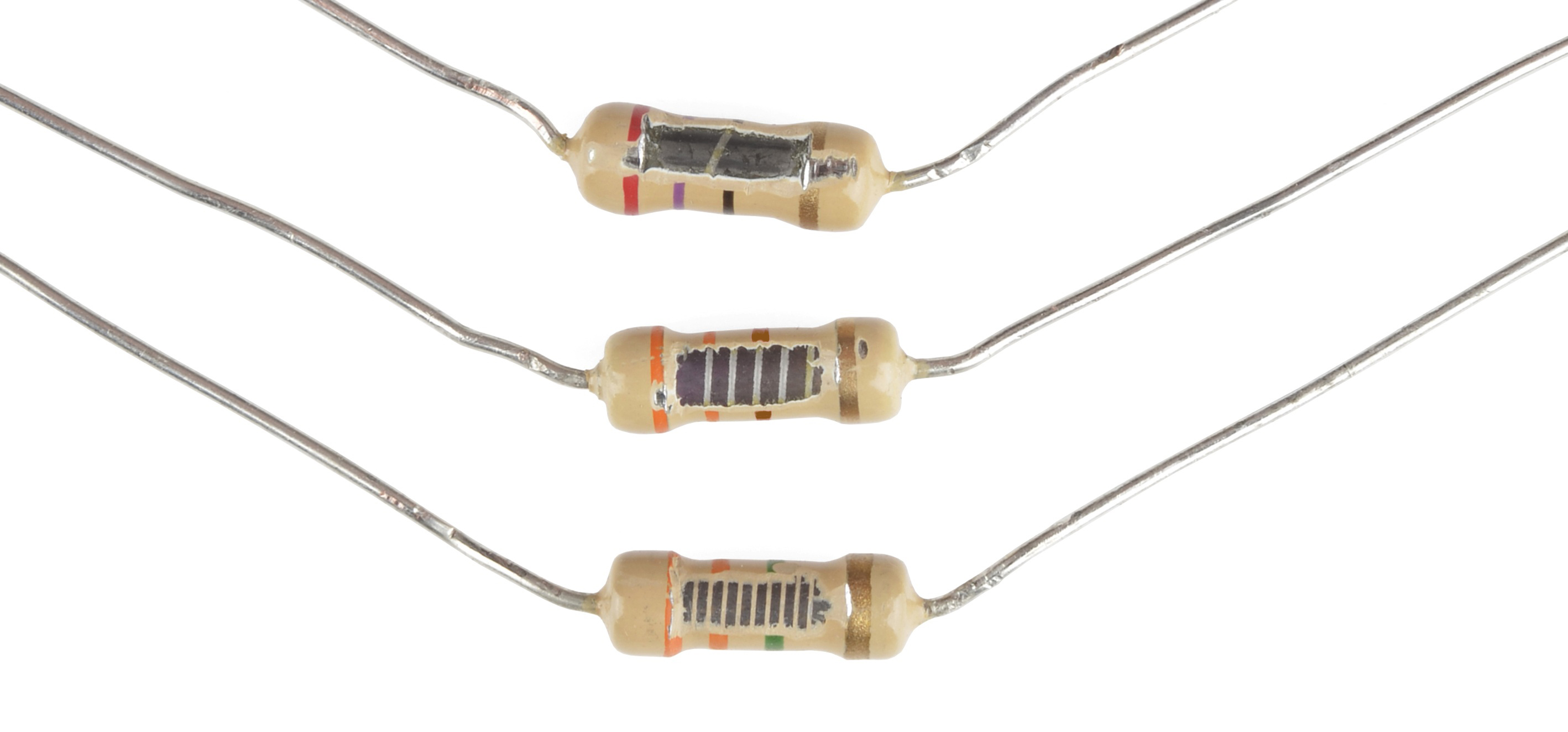
Peek inside the guts of a few carbon-film resistors. Resistance values from top to bottom: 27Ω, 330Ω and a 3.3MΩ. Inside the resistor, a carbon film is wrapped around an
insulator. More wraps means a higher resistance. Pretty neat!
Other through-hole resistors might be wirewound or made of super-thin metallic foil. These resistors are usually more expensive, higher-end components specifically chosen
for their unique characteristics like a higher power-rating, or maximum temperature range.
Surface-mount resistors are usually either thick or thin-film variety. Thick-film is usually cheaper but less precise than thin. In both resistor types, a small film of resistive
metal alloy is sandwiched between a ceramic base and glass/epoxy coating, and then connected to the terminating conductive edges.
Special resistor packages
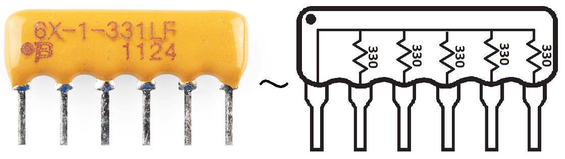
There are a variety of other, special-purpose resistors out there. Resistors may come in pre-wired packs of five-or-so resistor arrays. Resistors in these arrays may share a
common pin, or be set up as voltage dividers.
An array of five 330Ω resistors, all tied together at one end.
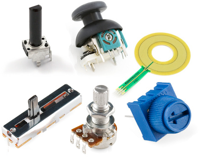
Resistors don’t have to be static either. Variable resistors, known as rheostats, are resistors which can be adjusted between a specific range of values. Similar to the rheostat
is the potentiometer. Pots connect two resistors internally, in series, and adjust a center tap between them creating an adjustable voltage divider. These variable resistors are
often used for inputs, like volume knobs, which need to be adjustable.
A smattering of potentiometers. From top-left, clockwise: a standard 10k trimpot, 2-axis joystick, softpot, slide pot, classic right-angle, and a breadboard friendly 10k trimpot.
Decoding Resistor Markings
Though they may not display their value outright, most resistors are marked to show what their resistance is. PTH resistors use a color-coding system (which really adds some
flair to circuits), and SMD resistors have their own value-marking system.
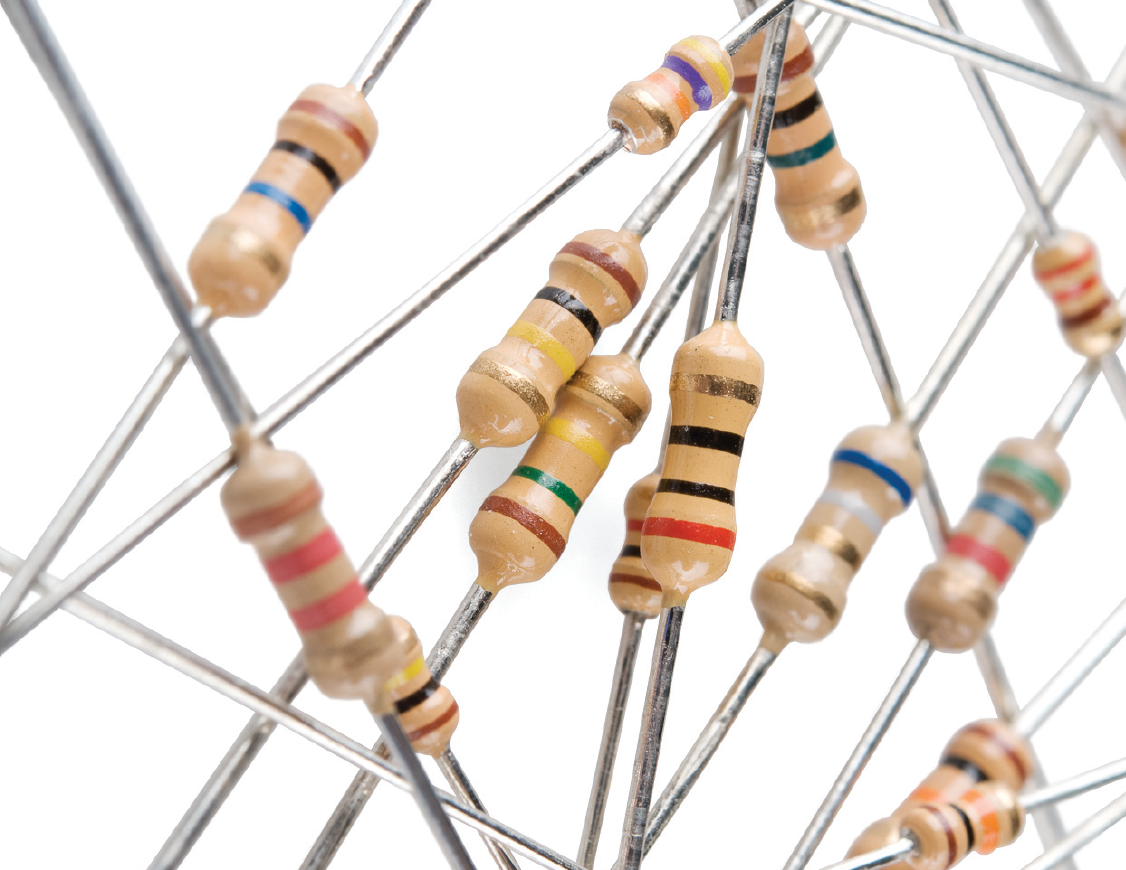
Decoding the color bands
Through-hole, axial resistors usually use the color-band system to display their value. Most of these resistors will have four bands of color circling the resistor.
The first two bands indicate the two most-significant digits of the resistor’s value. The third band is a weight value, which multiplies the two significant digits by a power of
ten.
The final band indicates the tolerance of the resistor. The tolerance explains how much more or less the actual resistance of the resistor can be compared to what its nominal
value is. No resistor is made to perfection, and different manufacturing processes will result in better or worse tolerances. For example, a 1kΩ resistor with 5% tolerance could
actually be anywhere between 0.95kΩ and 1.05kΩ.
How do you tell which band is first and last? The last, tolerance band is often clearly separated from the value bands, and usually it’ll either be silver or gold.
Here’s a table of each of the colors and which value, multiplier or tolerance they represent: