
Data Sheet


bq2407x
TS
TEMP
PACK+
PACK-
+
+
V
HOT
V
COLD
I
NTC
R
P
R
S
( )
( )
H TH S
TS TH S H
V R R
Rp
I R R V
´ +
=
´ + -
2
H C
TH TC TH TC TH TC TC TH
H C TS
V V
(R + R ) (R +R ) 4 R R + (R R )
(V V ) I
Rs =
2
æ ö
ì ü
´
- ± - ´ ´ -
ç ÷
í ý
ç ÷
- ´
î þ
è ø
bq24072
,
bq24073
,
bq24074
,
bq24075
,
bq24079
SLUS810K –SEPTEMBER 2008–REVISED MARCH 2015
www.ti.com
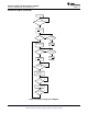
The allowed temperature range for 103AT-2 type thermistor is 0°C to 50°C. However, the user may increase the
range by adding two external resistors. See Figure 24 for the circuit details. The values for Rs and Rp are
calculated using the following equations:
(8)
where
• R
TH
: Thermistor Hot Trip Value found in thermistor data sheet
• R
TC
: Thermistor Cold Trip Value found in thermistor data sheet
• V
H
: IC's Hot Trip Threshold = 0.3 V nominal
• V
C
: IC's Cold Trip Threshold = 2.1 V nominal
• I
TS
: IC's Output Current Bias = 75 µA nominal
• NTC Thermsitor Semitec 103AT-4 (9)
Rs and Rp 1% values were chosen closest to calculated values in Table 3.
Table 3. Calculated Values
Cold Temp Resistance and Hot Temp Resistance and Trip
External Bias Resistor, Rs (Ω) External Bias Resistor, Rp (Ω)
Trip Threshold; Ω (°C) Threshold; Ω (°C)
28000 (–0.6) 4000 (51) 0 ∞
28480 (–1) 3536 (55) 487 845000
28480 (–1) 3021 (60) 1000 549000
33890 (–5) 4026 (51) 76.8 158000
33890 (–5) 3536 (55) 576 150000
33890 (–5) 3021 (60) 1100 140000
RHOT and RCOLD are the thermistor resistance at the desired hot and cold temperatures, respectively. The
temperature window cannot be tightened more than using only the thermistor connected to TS, it can only be
extended.
Figure 24. Extended TS Pin Thresholds
26 Submit Documentation Feedback Copyright © 2008–2015, Texas Instruments Incorporated
Product Folder Links: bq24072 bq24073 bq24074 bq24075 bq24079