
Data Sheet


bq24072
,
bq24073
,
bq24074
,
bq24075
,
bq24079
www.ti.com
SLUS810K –SEPTEMBER 2008–REVISED MARCH 2015
Feature Description (continued)
9.3.5.2 Adjustable Termination Threshold (ITERM Input, bq24074)
The termination current threshold in the bq24074 is user-programmable. Set the termination current by
connecting a resistor from ITERM to VSS. For USB100 mode (EN1 = EN2 = Low), the termination current value
is calculated as:
I
TERM
= 0.01 × R
ITERM
/ R
ISET
(4)
In the other input current limit modes (EN1 ≠ EN2), the termination current value is calculated as:
I
TERM
= 0.03 × R
ITERM
/ R
ISET
(5)
The termination current is programmable up to 50% of the fastcharge current. The R
ITERM
resistor must be less
than 15 kΩ. Leave ITERM unconnected to select the default internally set termination current.
9.3.5.3 Termination Disable (TD Input, bq24072, bq24073)
The bq24072 and bq24073 contain a TD input that allows termination to be enabled/ disabled. Connect TD to a
logic high to disable charge termination. When termination is disabled, the device goes through the pre-charge,
fast-charge and CV phases, then remains in the CV phase. During the CV phase, the charger maintains the
output voltage at BAT equal to V
BAT(REG)
, and charging current does not terminate. The charge current is set by
I
CHG
or I
IN
max, whichever is less. Battery detection is not performed. The CHG output is high impedance once
the current falls below I
TERM
and does not go low until the input power or CE are toggled. When termination is
disabled, the pre-charge and fast-charge safety timers are also disabled. Battery pack temperature sensing (TS
pin functionality) is disabled if the TD pin is high and the TS pin is unconnected or pulled up to V
IN
.
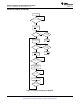
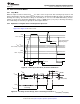
9.3.5.4 Battery Detection and Recharge
The bq2407x automatically detects if a battery is connected or removed. Once a charge cycle is complete, the
battery voltage is monitored. When the battery voltage falls below V
RCH
, the battery detection routine is run.
During battery detection, current (I
BAT(DET)
) is pulled from the battery for a duration t
DET
to see if the voltage on
BAT falls below V
LOWV
. If not, charging begins. If it does, then it indicates that the battery is missing or the
protector is open. Next, the precharge current is applied for t
DET
to close the protector if possible. If V
BAT
< V
RCH
,
then the protector closed and charging is initiated. If V
BAT
> V
RCH
, then the battery is determined to be missing
and the detection routine continues.
9.3.5.5 Battery Disconnect (SYSOFF Input, bq24075, bq24079)
The bq24075 and bq24079 feature a SYSOFF input that allows the user to turn the FET Q2 off and disconnect
the battery from the OUT pin. This is useful for disconnecting the system load from the battery, factory
programming where the battery is not installed or for host side impedance track fuel gauging, such as bq27500,
where the battery open circuit voltage level must be detected before the battery charges or discharges. The
/CHG output remains low when SYSOFF is high. Connect SYSOFF to VSS, to turn Q2 on for normal operation.
SYSOFF is internally pulled to VBAT through ~5 MΩ resistor.
9.3.5.6 Dynamic Charge Timers (TMR Input)
The bq2407x devices contain internal safety timers for the pre-charge and fast-charge phases to prevent
potential damage to the battery and the system. The timers begin at the start of the respective charge cycles.
The timer values are programmed by connecting a resistor from TMR to VSS. The resistor value is calculated
using the following equation:
t
PRECHG
= K
TMR
× R
TMR
(6)
t
MAXCHG
= 10 × K
TMR
× R
TMR
(7)
Leave TMR unconnected to select the internal default timers. Disable the timers by connecting TMR to VSS.
Reset the timers by toggling the CE pin, or by toggling EN1, EN2 pin to put the device in and out of USB
suspend mode (EN1 = HI, EN2 = HI).
Note that timers are suspended when the device is in thermal shutdown, and the timers are slowed proportionally
to the charge current when the device enters thermal regulation. For the bq24072 and bq24073, the timers are
disabled when TD is connected to a high logic level.
During the fast charge phase, several events increase the timer durations.
Copyright © 2008–2015, Texas Instruments Incorporated Submit Documentation Feedback 23
Product Folder Links: bq24072 bq24073 bq24074 bq24075 bq24079