
Data Sheet
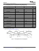

t
SU(STA)
SCL
SDA
t
w(H)
t
w(L)
t
f
t
r
t
(BUF)
t
r
t
d(STA)
REPEATED
START
t
h(DAT)
t
su(DAT)
t
f
t
su(STOP)
STOP START
bq27441-G1
SLUSBH1C –NOVEMBER 2013–REVISED DECEMBER 2014
www.ti.com
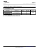
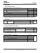
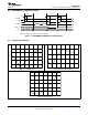
8.11 I
2
C-Compatible Interface Communication Timing Characteristics
T
A
= –40°C to 85°C; typical values at T
A
= 30°C and V
REGIN
= 3.6 V (unless otherwise noted) (Force Note1)
(1)
MIN TYP MAX UNIT
Standard Mode (100 kHz)
t
d(STA)
Start to first falling edge of SCL 4 μs
t
w(L)
SCL pulse duration (low) 4.7 μs
t
w(H)
SCL pulse duration (high) 4 μs
t
su(STA)
Setup for repeated start 4.7 μs
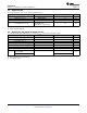
t
su(DAT)
Data setup time Host drives SDA 250 ns
t
h(DAT)
Data hold time Host drives SDA 0 ns
t
su(STOP)
Setup time for stop 4 μs
t
(BUF)
Bus free time between stop and start Includes Command Waiting Time 66 μs
t
f
SCL or SDA fall time
(1)
300 ns
t
r
SCL or SDA rise time
(1)
300 ns
f
SCL
Clock frequency
(2)
100 kHz
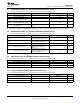
Fast Mode (400 kHz)
t
d(STA)
Start to first falling edge of SCL 600 ns
t
w(L)
SCL pulse duration (low) 1300 ns
t
w(H)
SCL pulse duration (high) 600 ns
t
su(STA)
Setup for repeated start 600 ns
t
su(DAT)
Data setup time Host drives SDA 100 ns
t
h(DAT)
Data hold time Host drives SDA 0 ns
t
su(STOP)
Setup time for stop 600 ns
t
(BUF)
Bus free time between stop and start Includes Command Waiting Time 66 μs
t
f
SCL or SDA fall time
(1)
300 ns
t
r
SCL or SDA rise time
(1)
300 ns
f
SCL
Clock frequency
(2)
400 kHz
(1) Specified by design. Not production tested.
(2) If the clock frequency (f
SCL
) is > 100 kHz, use 1-byte write commands for proper operation. All other transactions types are supported at
400 kHz. (See I
2
C Interface and I
2
C Command Waiting Time.)
Figure 1. I
2
C-Compatible Interface Timing Diagrams
8 Submit Documentation Feedback Copyright © 2013–2014, Texas Instruments Incorporated
Product Folder Links: bq27441-G1