
Data Sheet

bq27441-G1
SLUSBH1C –NOVEMBER 2013–REVISED DECEMBER 2014
www.ti.com
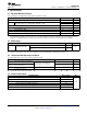
8.5 Supply Current
T
A
= 30°C and V
REGIN
= V
BAT
= 3.6V (unless otherwise noted)
PARAMETER TEST CONDITIONS MIN TYP MAX UNIT
I
CC
(1)
NORMAL mode current I
LOAD
> Sleep Current
(2)
93 μA
I
SLP
(1)
SLEEP mode current I
LOAD
< Sleep Current
(2)
21 μA
I
HIB
(1)
HIBERNATE mode current I
LOAD
< Hibernate Current
(2)
9 μA
Fuel gauge in host commanded
I
SD
(1)
SHUTDOWN mode current SHUTDOWN mode. 0.6 μA
(LDO regulator output disabled)
(1) Specified by design. Not production tested.
(2) Wake Comparator Disabled.
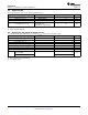
8.6 Digital Input and Output DC Characteristics
T
A
= –40°C to 85°C, typical values at T
A
= 30°C and V
REGIN
= 3.6 V (unless otherwise noted)(Force Note1)
(1)
PARAMETER TEST CONDITIONS MIN TYP MAX UNIT
V
IH(OD)
Input voltage, high
(2)
External pullup resistor to V
PU
V
PU
× 0.7 V
V
IH(PP)
Input voltage, high
(3)
1.4 V
V
IL
Input voltage, low
(2) (3)
0.6 V
V
OL
Output voltage, low
(2)
0.6 V
I
OH
Output source current, high
(2)
0.5 mA
I
OL(OD)
Output sink current, low
(2)
–3 mA
C
IN
(1)
Input capacitance
(2)(3)
5 pF
Input leakage current
0.1
(SCL, SDA, BIN)
I
lkg
μA
Input leakage current (GPOUT) 1
(1) Specified by design. Not production tested.
(2) Open Drain pins: (SCL, SDA, GPOUT)
(3) Push-Pull pin: (BIN)
6 Submit Documentation Feedback Copyright © 2013–2014, Texas Instruments Incorporated
Product Folder Links: bq27441-G1