
User Manual


Page 6
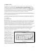
the output with pyro-generated signal. If a very long time constant is in use, then the film will
generate a voltage corresponding to the change in temperature since switch-on. Since the output
will be several volts per degree C, substantial offsets may be noticed.
In general, however, most piezo applications will have a cut-off frequency of several Hertz or more.
Connecting a device of 1nF capacitance to an oscilloscope input, even at 10 MΩ impedance, will
produce a roll off below 16 Hz. Only a more rapid change in the film temperature will generate a
detectable signal.
Common-mode rejection can be used to isolate either very low frequency mechanical strain from
simultaneous pyro-effects or vice-versa. These straight-forward techniques are quite familiar to MSI
applications engineers who are available for design assistance.
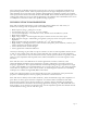
Electrical Design Considerations
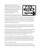
A useful model for piezo film which applies for most cases except ultrasonic applications is a strain-
dependent voltage source in series with a capacitance. Thus any resistive load will form a divider
network with a simple RC high-pass filter characteristic. The cut-off frequency is given by
and the time constant τ = RC. Operation below the cut-off frequency will give an
f
o
1
2π RC
output signal proportional to the rate of change of the input parameter (differentiator). Application
of a constant stress will generate an initial level followed by an exponential decay of rate exp(RC)
-1
.
A capacitive load will extend the time constant but reduce the magnitude of the response. Energy is
always lost when transferring charge from one capacitor to another. Large capacitive loads are
useful for attenuating the very large signals arising from powerful impacts—often hundreds of volts.
When driving the film at high voltage and high frequency, the dissipation factor of the film may
result in substantial energy loss in the form of heat. Also, the surface resistivity of the electrodes
may become significant, especially with vacuum metallized film. Very high localized currents may
be encountered. Operation within the field limits given in the Technical Manual is strongly
recommended since any arcing will normally destroy the device.
Silver ink, screenprinted onto both film surfaces, has been developed to withstand high voltage and
high localized currents. The silver ink metallization has been successfully used in tweeters and active
vibration damping applications. The DT1 sample is electroded with the silver ink. The unmetallized
border mitigates potential for arcing across the film's thickness. The offset lead attach tabs also
preclude high voltage breakdown, as the conductor at each lead attach site is on one side only.
Mechanical Design Considerations
The output energy is proportional to the volume of film stressed. Film thickness may be chosen to
optimize the electrical signal or in view of mechanical strength considerations. Thicker films generate
higher voltages but form smaller capacitors, so a laminate of thinner film with a compatible, passive
material such as polyester (i.e. the LDT1-028K) may be preferable to a single thicker film. Any area
of film that is not undergoing stress will act as a capacitive load on the "active" area and should be
minimized if required.
Most metallizations are subject to corrosion, especially when handled. Thin conformal coatings or
laminates are frequently applied to maintain surface quality. Acrylics adhesives, synthetic rubber
resins, epoxies and cyano-acrylates are all frequently employed in lamination and assembly.
Some designs may use external metallic or conductive substrates as the electrodes, in which case
unmetallized film may be used to good advantage. The external metal surface can be in direct