
User Manual

Page 54
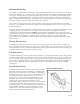
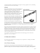
Figure 62. Air ranging ultrasound transducers
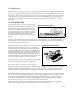
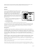
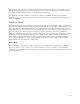
Figure 63. Air-ranging directivity patterns
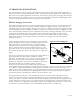
The presence of fluid couples the transmit signal to the receiver to a much greater extent (60dB) than
when the ultrasound energy is coupled by the air above the fluid. The excitation signal for the
transmitter is a 1.1 MHz sine wave tone burst with an amplitude of 20 volts peak to peak. The required
circuitry consists of a high frequency oscillator and clock, an array of analog switches, a single receiver
amplifier with input gate, and a threshold detector. These electronics can be reduced to the chip level,
and are incorporated on the backside of the circuit board.
Resolution of the level sensor is determined by the resolution of the patterned transmit electrodes on
the circuit board. Parallel elements of 2 mm width and 0.5 mm spacing between elements is a
representative capability. The ground electrode for the transmitters is a fully gold metallized surface on
the fluid side of the piezo film transmitter array. The receiver is formed by the same piece of piezo film,
capacitively coupled to the signal electrode which is a separate conductor trace on the printed circuit
board (PCB). Again, the ground is the backside electrode on the film.
The new level sensor has several unique advantages. The spacing between transmitter elements need not
be uniform For tanks that do not have a uniform volume throughout the tank height, a simple PCB
layout can linearize the nonlinear tank volume by setting the transmitter element spacing accordingly.
The output of the device is digital—no expensive A/D conversion is required. The level sensor is small
in width, less than 1 inch, so it can be inserted into a small
diameter tube. The tube confines the motion of the fluid,
reducing large swings in fluid height readings caused by
motion, as with an automobile fuel tank during cornering.
Reliability is greatly improved. The level sensor is self
diagnostic to the extent that the transmitter/receiver pair
must be operational to deliver a meaningful signal. The
absence of the signal indicates a fault condition. For a
detailed discussion on Ultrasonic Ink Level Sensing, see
Appendix C.
Air Ranging Ultrasound
Ultrasonic devices used in pulse-echo modes are used in robotics, vehicle safety and control system,
object recognition systems and other remote distance measurement devices. The sensors provide high
resolution in the targeted direction, and can be used to measure the elapsed time from transmit to
receive to determine the distance to an object. Unlike piezo ceramic and electrostatic devices, piezo film
can deliver a very short pulse (due to its low Q), allowing the
same device to be used as both transmitter and receiver, even in
the near field of the transducer.
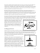
Multiple piezo film elements can be easily fabricated, as shown
in Figure 62. The geometries of these cylindrically shaped
elements (length, radius of curvature, number of elements) can
be designed to control the directivity pattern and acoustic
properties. Transducers with operating frequencies from 40-200
KHz have been made. Average values of transducer sensitivity
are 0.1-1 mV/Pa in the receive mode (noise was < 1µV) and 15-
75 mPa/Vcm
2
in the transmit mode for 1 m of distance. The
minimum distances measured in pulse-echo mode was 30 mm.
Distances to 15 meters have been measured with a main beam
width of less than 10 degrees, and maximum side lobe
amplitudes that are 12 dB down at 60 KHz. Examples of
directivity patterns for single and multiple element transducers are shown in Figure 63. Multiple