
User Manual

Page 42
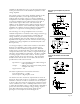
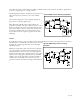
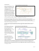
Figure 49. CMOS circuit for detecting a single impact
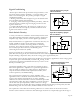
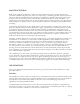
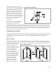
Figure 50. CMOS interface circuit for counting
applications
input bias resistance, and the effect of EMI. A CMOS circuit can be used, for example, in applications
to sense a single impact or a single pressure.
The D-Flip Flop in Figure 49 indicates the presence of
either the impact or pressure to set off an audible
alarm.
The circuit in Figure 50, senses multiple impacts or
pressures for counting applications.
Many different CMOS circuit configurations are
possible to interface with piezo film. Common to all of
them is an input bias resistor in parallel with the piezo
film, and an input resistor in series with the film. The
bias resistor handles leakage current and the series
resistor limits current to protect against electrostatic
discharge.
Cables
In applications where it is not possible to place the amplification circuit in close proximity to the piezo
film transducer, considerable care must be exercised in
selecting the connecting cable that carries the high-
impedance signal.
Shielded coaxial cable, while used for noise reduction,
can add problems associated with cable leakage and
added capacitance. In most cases the cable's primary
insulation should consist of highly resistant, non-polar
plastics such as high-purity polyethylene or Teflon®
(PTFE). It is equally important to make the cable as
vibration-free as possible since cable movements
generate noise that interferes with signal transmission.