
User Manual

Page 39
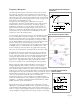
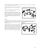
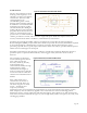
Figure 41. Typical amplifiers for piezo film
sensors
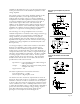
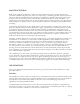
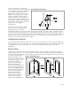
Figure 42. An interface circuit of a traffic
sensor
amplifier is determined by Q/C
f
. Q is the charge developed
on the piezo film and C
f
is the feedback capacitance of the
charge amplifier.
The output voltage of the charge amplifier depends on the
feedback capacitance, not the input capacitance. This
indicates that the output voltage of a charge amplifier is
independent of the cable capacitance. The major advantage
of a charge amplifier can be realized when a long cable is
used between a piezo film sensor and electronics. In
addition, it also minimizes charge leakage through the stray
capacitance around the sensor. Otherwise, simple voltage
amplifiers are sufficient for most applications. Included in
Figure 41 is a typical non-inverting voltage amplifier.
The advantage of a voltage amplifier can be seen when
ambient temperature is considered. The voltage sensitivity (g-
constant) variation over temperature is smaller than the
charge sensitivity (d-constant) variation. Consequently,
voltage amplifiers with piezo film exhibit less temperature
dependence. In Figure 41, the time constants for the charge
amplifier and voltage amplifier are determined by RC
f
and
RC respectively.
As a design example, a traffic sensor interface is described.
Because of its flexibility, piezo cable is an ideal sensor
material for traffic measurement applications. MSI’s BL
traffic sensor is constructed with a piezo cable sheathed in a
compressed brass tube, with a variety of signal cable lengths
tailored to the installation requirements. The BL is available
in sensing lengths of more than 3 meters. In this specific
example, the BL sensor is 2 meters long. This electrically
shielded sensor has 100 feet of coax cable. The electrical
specifications of this sensor include:
Capacitance = 9.5 nF (including piezo cable and signal
cable capacitances)
Output = 500mV (for a wheel load of 800 pounds
at 55mph and 70°F)
Signal : Noise = 10:1
The basic requirements of an interface circuit are:
Low end frequency = 1.6 Hz
Circuit output = Digital pulse count
An interface circuit to meet these requirements is shown in
Figure 42. This circuit works as a comparator. A 10MΩ input
resistance is chosen in order to reduce the cut-off frequency
to about 1 Hz. The actual cut-off frequency with this resistor
can be calculated as 1.6 Hz. A 10MΩ potentiometer is used
to adjust the threshold voltage, V and the diode is included to
protect the electronics from high voltage damage. Typical
piezo film and interface circuit output signals from a
passenger car at 55 mph are shown in Figure 42.