
User Manual

Page 38
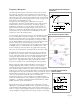
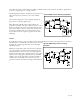
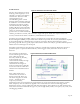
Figure 38. High pass filter characteristic
of piezo film
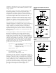
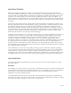
Figure 39. Frequency response of SDT1
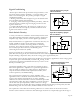
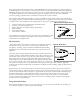
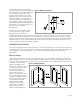
Figure 40. Unity gain buffer for
piezo film sensors
Frequency Response
Another important aspect of the time constant can be seen in
the frequency response of the equivalent circuit. The circuit
exhibits an RC high-pass filter characteristic as shown in Figure
38. In this figure, the vertical axis implies the ratio of observable
output signal to the developed signal (open circuit voltage of the
piezo film). Zero dB implies no loss
of signal. The cutoff frequency (3 dB down) is inversely
proportional to the time constant. When a piezo film sensor is
operated below this cut-off frequency, the output signal is
significantly reduced. For a low frequency measurement, an
input resistance needs to be high enough so that the cut-off
frequency is well below the desired operating frequency. This
consequence can be verified from consideration of the time
constant as well as the loading effect.
As an example, the frequency response of a shielded piezo film
sensor (model SDT1) is shown in Figure 39. In this example,
the SDT is interfaced with a circuit which contains a 10MΩ
load resistor and an FET. The capacitance of the piezo film is
2.4 nF. With 10MΩ load resistance, the time constant becomes
24 msec and thus, the cut-off frequency is 6.6 Hz. For
comparison, the cut-off frequency can be reduced to 0.66 Hz if
a 100MΩ resistor is used instead of the 10MΩ resistor. This
sensor component can be used for any application operating
above the cut-off frequency determined by the resistance value.
In applications where the electronic circuit cannot be placed
near the sensor, a buffer circuit is recommended close to the
sensor. The buffer circuit converts the high output impedance
of the piezo film element into a low output impedance and
thus minimizes the signal loss and noise through the cable. For
large size (i.e., high capacitance) piezo film sensors a buffer
may not be required, even with small signals and long cables.
When a high piezo film output impedance is required, a low-
leakage, high impedance buffer is necessary. For example,
infrared motion sensor and accelerometer applications require
up to 50GΩ of input resistance to obtain a very low frequency
response. For such cases, the input impedance of the buffer must be
much higher than the output resistance of the piezo film in order to
maintain the low frequency response. In addition, minimum leakage
current of the buffer is critical in order to maximize the
measurement accuracy. Some examples of low leakage buffer
electronics include: JFET - 4117 (Siliconix, Sprague); Operational
amplifiers — LMC660, LF353 (National Semiconductor), OP80
(PMI), and 2201 (Texas Instruments).
Figure 40 shows unity gain buffer circuit examples for general
applications. Operational amplifiers offer a great deal of versatility
as both buffers and amplifiers. They can be used as either charge-
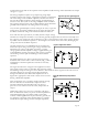
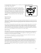
mode or voltage-mode amplifiers. Figure 41 shows basic charge and
voltage amplifier configurations. The voltage output of the charge