
User Manual

Page 37
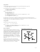
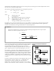
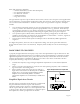
Figure 35. Equivalent circuit for piezo film
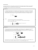
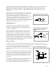
Figure 36. Equivalent circuit of piezo film
with input resistance of electronic
interface
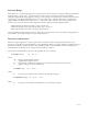
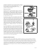
Figure 37. Time response of piezo film
permittivity and area and inversely proportional to film thickness. The voltage source amplitude is
equal to the open circuit voltage of piezo film and varies from microvolts to 100's of volts,
depending on the excitation magnitude. This simplified equivalent circuit is suitable for most
applications but is of limited value at very high frequencies such as that used in ultrasound
transducers.
Figure 35 shows an equivalent circuit as a charge generator.
This equivalent circuit has film capacitance C
f
, and internal
film resistance R
f
. The induced charge Q is linearly
proportional to the applied force as described earlier. The
capacitance C
f
is proportional to the surface area of film and
is inversely proportional to the film thickness. In low
frequency applications, the internal film resistance R
f
is very
high and can be ignored. The open circuit output voltage can
be found from the film capacitance; i.e., V=Q/C
f
.
Input Resistance
The most critical part of an interface circuit is the input
resistance. The input resistance affects low frequency
measurement capability as well as signal amplitude. This is
called the "loading effect".
Piezo film capacitance can be regarded as an equivalent
source impedance. It is important to note that this source
impedance increases with decreasing film capacitance and
decreasing frequency of operation. This source impedance
combined with the input resistance produces a voltage
divider. As the ratio of input resistance to source impedance
is decreased, the overall output voltage is reduced. Therefore,
choosing a proper input resistance for the electronic interface
is critical in minimizing the loading effect.
Time Constant
In addition to input resistance, the input capacitance of an interface circuit can also affect the
output. Figure 36 shows the equivalent circuit of film with input resistance R
i
and input capacitance
C
i
. A typical time domain response of piezo film is shown in
Figure 37 . The charge developed on the film due to an
applied force decays with a time constant which is defined by
R
i
(C
f
+ C
i
).
This time constant represents the time required for a signal to
decay to 70.7% (-3dB) of its original amplitude. The smaller
the time constant, the quicker the signal decays. Because of
this finite time constant, piezo film is suitable for dynamic
measurements rather than static measurement (0.001 Hz
minimum).
If a long time constant is desired, a high input resistance and
film capacitance can be used. It should be understood,
however, that a high input resistance can also produce higher
noise, requiring compensation through shielding, etc.