
User Manual

Page 28
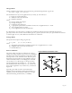
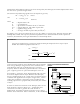
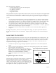
Figure 28. Numerical classification of axes
Charge Mode:
Under conditions approaching a short circuit, the generated charge density is given by:
D = Q/A = d
3n
X
n
(n = 1, 2, or 3)
The mechanical axis (n) of the applied stress (or strain), by convention, is:
1 = length (or stretch) direction
2 = width (or transverse) direction
3 = thickness direction
where
D = charge density developed
Q = charge developed
A = conductive electrode area
d
3n
= appropriate piezoelectric coefficient for the axis of applied stress or strain
n = axis of applied stress or strain
X
n
= stress applied in the relevant direction
It is important to note that the d
3n
coefficient is commonly expressed in pico-Coulombs per Newton
(pC/N), but the more correct form would be (pC/m
2
)/(N/m
2
) since the areas (m
2
) upon which the stresses
or strains apply are very often different and cannot be "canceled".
Voltage Mode:
The open-circuit output voltage is given by:
V
o
= g
3n
X
n
t (n = 1, 2, or 3, as above)
where
g = appropriate piezoelectric coefficient for the axis of applied stress or strain
X
n
= applied stress in the relevant direction
t = the film thickness
Piezo Coefficients:
The most widely used piezo coefficients, d
3n
and g
3n
,
charge and voltage respectively, possess two subscripts.
The first refers to the electrical axis, while the second
subscript refers to the mechanical axis. Because piezo
film is thin, the electrodes are only applied to the top
and bottom film surfaces. Accordingly, the electrical
axis is always "3", as the charge or voltage is always
transferred through the thickness (n = 3) of the film.
The mechanical axis can be either 1, 2, or 3, since the
stress can be applied to any of these axes, as shown in
Figure 28.
Typically, piezo film is used in the mechanical 1
direction for low frequency sensing and actuation (<
100KHz) and in the mechanical 3 direction for high
ultrasound sensing and actuation (> 100KHz).