
User Manual

Page 17
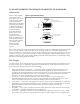
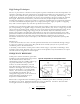
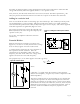
Figure 15. Magnitude response of R-C filter
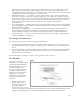
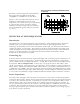
Figure 16. Phase response of R-C filter
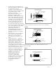
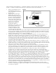
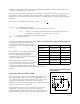
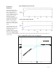
Figure 17. Magnitude response shown as log/log plot
Frequency
Response
This is illustrated in the
following example graphs.
First, a lin/lin plot is
shown (Figure 15, linear y-
scale or amplitude, plotted
against linear x-scale or
frequency) with the
corresponding phase plot
(Figure 16) also shown in
lin/lin form. Following
these is a log/log plot
(Figure 17), which will be
dealt with in a little greater
detail.
Note that the phase curve
indicates that at very low
frequencies, the observed
voltage will show
significant phase deviation
from the source (limiting at
-90
o
or -π/2 radians at "dc"
or zero Hz). The significance of this effect is great if the piezo film element is to be used as part of a
control loop.