
User Manual

Page 16
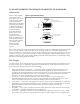
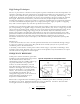
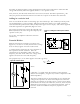
Figure 13. Adding the oscilloscope as resistive
load
V
L
R
L
R
L
Z
C
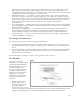
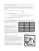
Figure 14. Potential divider
Z
C
jX
C
j
2πfC
this article to elaborate further on the calculations involved, but it is important to realize that this
voltage will absolutely follow the applied stimulus - it is a "perfect" source.
Note, however, that the node marked "X" can never be accessed! The film's capacitance C
0
will
always be present and connected when we monitor the "output" of the film at the electrodes.
Adding in a resistive load
Now we can add in the effect of connecting up to the oscilloscope. The oscilloscope and its probe
are modeled simply as a pure resistance, although in reality there will be a very small capacitance
associated with the probe and the cable (usually in the region of 30 to 50 pF). This can be neglected
if the film capacitance is significantly higher in value.
The voltage measured across the load resistor R
L
will
not necessarily be the same voltage developed by the
"perfect" source (V
S
).
To see why, it is helpful to redraw this circuit in
another way.
Potential Divider
With the circuit shown in Figure 13 redrawn as in
Figure 14, it is easier to see why the full source voltage
does not always appear across the resistive load.
A potential divider is formed by the series connection of
the capacitance and the resistance. Since the
capacitance has an impedance which varies with
frequency, the share of the full source voltage which
appears across R
L
also varies with frequency.
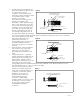
The proportion (V
L
) of V
S
which appears across R
L
is given by:
where
(j denoting B-1, and X
C
being the reactance of the capacitive
element. For simplicity, we ignore any resistive component of the
film's impedance).
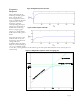
The above equations may be used in simple ways to calculate the
voltage level expected to be observed in simple cases where the
frequency of excitation is constant, and so a value of f can simply
be substituted. In many real-world cases, however, there may be a
distribution of signal energy over a band of frequencies. Then it
becomes useful to consider the "frequency response" of the
network.