
User Manual

Page 15
C …
A
t
Description Part No. Capacitance
LDT0-028K/L 0-1002794-1 500 pF
DT1-028K/L 1-1002908-0 1.3 nF
DT1-052K/L 2-1002908-0 650 pF
DT2-028K/L 1-1003744-0 2.6 nF
DT4-028K/L 1-1002150-0 9 nF
8" x 11" 28 µm 1-1003702-4 30 nF
HYD-CYL-100 0-1001911-1 43 pF
Table 3. Capacitance values of common piezo film components
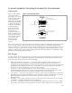
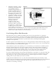
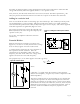
Figure 12. Piezo film element as a simple
voltage generator
PVDF has a high dielectric constant compared with most polymers, with its value being about 12
(relative to the permittivity of free space).
Obviously, the capacitance of an element will increase as its plate area increases, so a large sheet of
film will have a larger capacitance than a small element. Capacitance also increases as the film
thickness decreases, so for the same surface geometry, a thin film will have a higher capacitance than a
thick film.
These factors are formally related in the equation:
where C is the capacitance of the film,
… is the permittivity (which can also be expressed in the form
… = …
r
…
0
where ε
r
is the relative permittivity (about 12 for PVDF), and ε
0
is the
permittivity of free space (a constant, 8.854 x 10
-12
F/m)
A is the active (overlap) area of the film's electrodes
and t is the film thickness
The units of capacitance are Farads (F), but
usually much smaller sub-multiples are
encountered: microfarads (µF or 10
-6
F),
nanofarads (nF or 10
-9
F) and picofarads (pF
or 10
-12
F).
The capacitance of any piezo film element
can be calculated using the formula, or
measured directly using a hand-held
capacitance meter, or bench-top instrument
such as an "LCR bridge".
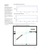
Capacitance values should be quoted at a
given measurement frequency - where this is
not given, a frequency of 1 KHz is often
assumed. Capacitance values of piezo film
components usually decrease as the measurement frequency
increases.
Equivalent Circuit of Piezo Film
We are now ready to draw out an electrical equivalent of the
piezo film element. There are two equally valid "models" - one
is a voltage source in series with a capacitance, the other a charge
generator in parallel with a capacitance - but the latter is
uncommon in electrical circuit analysis and we will concentrate
on the voltage source (see Figure 12).
The dashed line represents the "contents" of the piezo film
component. The voltage source V
S
is the piezoelectric
generator itself, and this source is directly proportional to the
applied stimulus (pressure, strain, etc). It is not the purpose of