
User Manual

Page 13
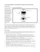
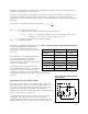
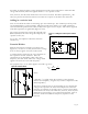
Figure 10. Clamped film in d31 mode produces sound
f
r
v
2t
2.2x 10
3
m/sec
2x 28x10
6
m
High Voltage Techniques
The use of piezo film as a vibration exciter requires separate consideration. Since the impedance of a
capacitive transducer decreases with frequency and approaches infinity for low frequencies, very high
voltages (a few hundred volts typically) may be required to drive, for example, full audio-range
loudspeakers. Frequently, transformers are used to step up moderate voltages to supply the required
drive signal. Under these circumstances, extreme stresses may be placed upon the connections.
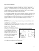
Consider first applying a voltage step of 30V to a capacitor of 100nF with an overall circuit resistance
of 2 ohms. The initial current pulse peaks at 15 amps (assuming the supply is capable of supplying
this). Such a current "spike" may well show up defects in connectors.
Consider next a transformer which steps 12V signals up to 240V. A DC current in the primary of 200
µA (corresponding to an applied voltage of 0.5 volts), when broken, may cause a voltage surge of 830
volts across the secondary circuit, well in the excess of the expected X 20 magnification factor. Even
with heavy capacitive loading, high voltages may be seen. Worse still, if the secondary circuit is
broken, current pulses exceeding 60A with durations of only tens of nanoseconds may arise. Such
phenomena should not trouble well-formed connections. But if a lead-attach method has been used
which has any trapped air, the effect of the reduced dielectric constant may be to promote
breakdown. Such events may be catastrophic, as the familiar crackling sound and lively blue sparks
will testify.
Solutions are:
1. Silver ink electrodes are a must - the thin sputtered electrodes cannot withstand the high voltages
2. Large area contacts to reduce stress. We paint silver ink around eyelets/rivets to provide extra
conduction paths to the film electrode.
3. (Possibly) a semi-resistive contact pad to reduce current surges—equivalent to including a series
resistance in the circuit. Practical values up to about 1 k will produce only a fractional loss in output
and will reduce the magnitude of current spikes.
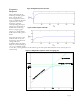
FREQUENCY RESPONSE
Unlike piezo ceramic transducers, piezo film
transducers offer wide dynamic range and are
also broadband. These wide band
characteristics (near dc to 2GHz) and low Q
are partly attributable to the polymers'
softness. As audio transmitters, a curved
piezo film element, clamped at each end,
vibrates in the length (d
31
) mode, as shown in
Figure 10. Piezo film is a very high fidelity
tweeter, also used in novelty speakers for
toys, inflatables and apparel. The d
31
configuration (Figure 10) is also used for air
ultrasound ranging applications up to
frequencies of about 50 KHz.
When used as a high ultrasonic transmitter (generally >500KHz), piezo film is normally operated in
the thickness (d
33
) mode. Maximum transmission occurs at thickness resonance. The basic half-
wavelength resonance of 28µm piezo film is about 40 MHz: