
User Manual


Page 7
contact with the unmetallized film to collect the charge, or, capacitive coupling through thin adhesive
tapes or epoxy layers can be employed for ac applications. Patterning of the electrodes is especially
useful for defining specific active areas on a continuous sheet and also to allow die-cutting of
elements with a clear border around the cut area. Displacement (offset) of upper and lower electrode
tabs at the connection point is good practice to prevent unpredictable piezo behavior in this area
caused by the influence of the wire terminations. This also allows low cost penetrative lead-attach
methods to be used (crimps or eyelets).
Joint Electrical and Mechanical Design Considerations
The capacitive nature of piezo film devices implies that they are susceptible to Electro Magnetic
Interference (EMI). This becomes increasingly more important as the output signal level drops.
EMI can be ignored where the output is high or when the film is being driven in a non-critical
environment. A.C. mains interference may become a problem with unshielded devices. Another
potential problem exists when one electrode element is being driven and an another is receiving the
vibration signal. Care must be taken to avoid "crosstalk".
Use of ready-made shielded elements (SDT1-028K) supplied with coaxial cable eliminates these
problems, but simple measures may be taken with any device to avoid interference.
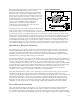
Unwanted frequencies may be filtered out electronically. If the sensor is to be mounted on a
conductive substrate, then this may form one half of a grounded envelope, with the outer electrode
forming the other half. Lightweight shielded cable is readily available and is an alternative to twisted
pair wires. Attention should be paid to the point of connection itself as this is also an area of EMI
vulnerability.
Durable lead attachment techniques have been fully developed by MSI, and most products are
supplied with leads preattached. As indicated, some form of coaxial cable is often employed and
must be interfaced to a very thin flexible material. Reinforcement at the lead attach site may be
required, which can introduce some acoustic effects into the transducer if the interconnection site is
free to vibrate.
Thin copper foil backed with a conductive adhesive can provide excellent but non-permanent
connections to the film. An area of 1 cm² will give a contact resistance of a few mΩ s. Crimp-
through connectors as used for flexible circuits are routinely used with offset electrode patterns, but
thin films require some physical reinforcement for good results. Polyester reinforcement at the lead
attach site is a common method to ruggedize the interconnection. The stiffener may lie between the
crimp and the electrode with only minor degradation of contact resistance. Typical values are
150-500 mΩ. Miniature rivets, eyelets and even nuts and bolts, with washers, all combine great
strength with good contact resistance at typically less than 100 mΩ. These techniques may be used to
connect to cables using solder tags, or direct onto printed circuit boards.
Clamping methods, either direct to the conductive traces on the PCB or using conductive rubber,
ZEBRA® connectors, lugs and washers have all been used with success. Direct connection using
silver-loaded (conductive) epoxy also works well, but requires curing time, often at elevated
temperature, for best results.
As indicated earlier, other materials may form the electrodes themselves, such as PCB traces or
conductive rubber. Capacitive coupling through thin adhesive layers is practical under some a.c.
circumstances, allowing some unusual transducer designs with apparently no lead attachment at all!
ZEBRA is a registered trademark of Fujipoly.