
Data Sheet
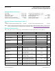
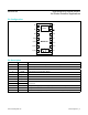

PIN NAME FUNCTION
1, 8, 14 N.C. No Connection. Connect to PCB pad for mechanical stability.
2 SCL I
2
C Clock Input
3 SDA I
2
C Clock Data, Bidirectional (Open-Drain)
4 PGND Power Ground of the LED Driver Blocks
5 R_DRV Red LED Driver
6 IR_DRV IR LED Driver
7 G_DRV Green LED Driver
9 V
LED+
LED Power Supply (anode connection). Use a bypass capacitor to PGND for best
performance.
10 V
LED+
11 V
DD
Analog Power Supply Input. Use a bypass capacitor to GND for best performance.
12 GND Analog Ground
13 INT Active-Low Interrupt (Open-Drain). Connect to an external voltage with a pullup resistor.
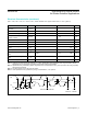
N.C. 1
SCL 2
SDA 3
PGND 4
R_DRV 5
IR_DRV 6
G_DRV 7
14
N.C.
13
INT
12
GND
11
V
DD
10
V
LED+
9
V
LED+
8
N.C.
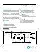
SENSOR
LEDs
MAX30105
Pin Description
Pin Conguration
www.maximintegrated.com
Maxim Integrated
│
9
MAX30105 High-Sensitivity Optical Sensor
for Smoke Detection Applications