
Data Sheet
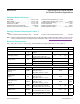
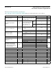
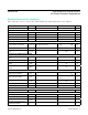

(V
DD
= 1.8V, V
LED+
= 5.0V, T
A
= -40°C to +85°C, unless otherwise noted. Typical values are at T
A
= 25°C.) (Note 2)
Note 2:
All devices are 100% production tested at T
A
= +25°C. Specifications over temperature limits are guaranteed by Maxim
Integrated’s bench or proprietary automated test equipment (ATE) characterization.
Note 3: Specifications are guaranteed by Maxim Integrated’s bench characterization and by 100% production test using proprietary
ATE setup and conditions.
Note 4: For design guidance only. Not production tested.
Note 5: These specifications are guaranteed by design, characterization, or I
2
C protocol.
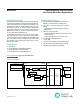
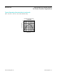
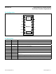
Figure 1. I
2
C-Compatible Interface Timing Diagram
PARAMETER SYMBOL CONDITIONS MIN TYP MAX UNITS
Hold Time (Repeated) START
Condition
t
HD,STA
0.6 µs
SCL Pulse-Width Low t
LOW
1.3 µs
SCL Pulse-Width High t
HIGH
0.6 µs
Setup Time for a Repeated
START Condition
t
SU,STA
0.6 µs
Data Hold Time t
HD;DAT
0 0.9 µs
Data Setup Time t
SU;DAT
100 ns
Setup Time for STOP Condition t
SU;STO
0.6 µs
Pulse Width of Suppressed
Spike
t
SP
50 ns
Bus Capacitance C
b
400 pF
SDA and SCL Receiving Rise
Time
T
r
(Note 5) 20 300 ns
SDA and SCL Receiving Fall
Time
t
Rf
(Note 5)
20 x V
DD
/5.5
300 ns
SDA Transmitting Fall Time t
of
20 x V
DD
/5.5
250 ns
SDA
SCL
t
HD,STA
START CONDITION
t
R
t
F
t
LOW
t
SU,DAT
t
HD,DAT
t
SU,STA
t
HD,STA
REPEATED START CONDITION
t
SP
t
SU,STO
t
BUF
STOP
CONDITION
START
CONDITION
t
HIGH
www.maximintegrated.com
Maxim Integrated
│
5
MAX30105 High-Sensitivity Optical Sensor
for Smoke Detection Applications
Electrical Characteristics (continued)