
Data Sheet

Power Sequencing and Requirements
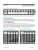
Power-Up Sequencing
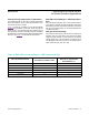
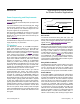
Figure 6 shows the recommended power-up sequence for
the MAX30105.
It is recommended to power the V
DD
supply first, before
the LED power supplies (V
LED+
). The interrupt and I
2
C
pins can be pulled up to an external voltage even when
the power supplies are not powered up.
After the power is established, an interrupt occurs to alert
the system that the MAX30105 is ready for operation.
Reading the I
2
C interrupt register clears the interrupt, as
shown in Figure 6.
Power-Down Sequencing
The MAX30105 is designed to be tolerant of any power
supply sequencing on power-down.
I
2
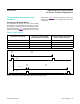
C Interface
The MAX30105 features an I
2
C/SMBus-compatible,
2-wire serial interface consisting of a serial data line
(SDA) and a serial clock line (SCL). SDA and SCL
facilitate communication between the MAX30105 and the
master at clock rates up to 400kHz. Figure 1 shows the
2-wire interface timing diagram. The master generates
SCL and initiates data transfer on the bus. The master
device writes data to the MAX30105 by transmitting the
proper slave address followed by data. Each transmit
sequence is framed by a START (S) or REPEATED
START (Sr) condition and a STOP (P) condition. Each
word transmitted to the MAX30105 is 8 bits long and is
followed by an acknowledge clock pulse. A master read-
ing data from the MAX30105 transmits the proper slave
address followed by a series of nine SCL pulses.
The MAX30105 transmits data on SDA in sync with the
master-generated SCL pulses. The master acknowl-
edges receipt of each byte of data. Each read sequence
is framed by a START (S) or REPEATED START (Sr)
condition, a not acknowledge, and a STOP (P) condition.
SDA operates as both an input and an open-drain output.
A pullup resistor, typically greater than 500Ω, is required
on SDA. SCL operates only as an input. A pullup resistor,
typically greater than 500Ω, is required on SCL if there are
multiple masters on the bus, or if the single master has an
open-drain SCL output. Series resistors in line with SDA
and SCL are optional. Series resistors protect the digital
inputs of the MAX30105 from high voltage spikes on the
bus lines and minimize crosstalk and undershoot of the
bus signals.
Bit Transfer
One data bit is transferred during each SCL cycle. The
data on SDA must remain stable during the high period of
the SCL pulse. Changes in SDA while SCL is high are control
signals. See the START and STOP Conditions section.
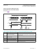
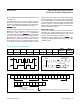
START and STOP Conditions
SDA and SCL idle high when the bus is not in use. A mas-
ter initiates communication by issuing a START condition.
A START condition is a high-to-low transition on SDA with
SCL high. A STOP condition is a low-to-high transition
on SDA while SCL is high (Figure 7). A START condition
from the master signals the beginning of a transmission
to the MAX30105. The master terminates transmission,
and frees the bus, by issuing a STOP condition. The bus
remains active if a REPEATED START condition is gener-
ated instead of a STOP condition.
Early STOP Conditions
The MAX30105 recognizes a STOP condition at any point
during data transmission except if the STOP condition
occurs in the same SCL high pulse as a START condi-
tion. For proper operation, do not send a STOP condition
during the same SCL high pulse as the START condition.
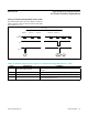
Slave Address
A bus master initiates communication with a slave device
by issuing a START condition followed by the 7-bit slave
ID. When idle, the MAX30105 waits for a START condition
followed by its slave ID. The serial interface compares
each slave ID bit by bit, allowing the interface to power
down and disconnect from SCL immediately if an incor-
rect slave ID is detected. After recognizing a START
condition followed by the correct slave ID, the MAX30105
is programmed to accept or send data. The LSB of the
slave ID word is the read/write (R/W) bit. R/W indicates
whether the master is writing to or reading data from the
MAX30105 (R/W = 0 selects a write condition, R/W = 1
selects a read condition). After receiving the proper slave
Figure 6. Power-Up Sequence of the Power Supply Rails
V
LED+
V
DD
INT
SDA, SCL
HIGH (I/O PULLUP )
HIGH (I/O PULLUP )
PWR_RDY INTERRUPT
READ TO CLEAR
INTERRUPT
www.maximintegrated.com
Maxim Integrated
│
29
MAX30105 High-Sensitivity Optical Sensor
for Smoke Detection Applications