
Data Sheet

The purpose of PILOT_PA[7:0] is to set the LED power during the proximity mode, as well as in Multi-LED mode.
Multi-LED Mode Control Registers (0x11–0x12)
In multi-LED mode, each sample is split into up to four time slots, SLOT1 through SLOT4. These control registers determine
which LED is active in each time slot, making for a very flexible configuration.
Each slot generates a 3-byte output into the FIFO. One sample comprises all active slots, for example if SLOT1 and
SLOT2 are non-zero, then one sample is 2 x 3 = 6 bytes. If SLOT1 through SLOT3 are all non-zero, then one sample
is 3 x 3 = 9 bytes.
The slots should be enabled in order (i.e., SLOT1 should not be disabled if SLOT2 or SLOT3 are enabled).
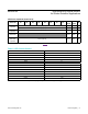
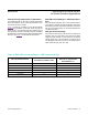
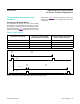
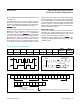
Table 9. Multi-LED Mode Control Registers
REGISTER B7 B6 B5 B4 B3 B2 B1 B0
REG
ADDR
POR
STATE
R/W
Multi-LED
Mode Control
Registers
SLOT2[2:0] SLOT1[2:0] 0x11 0x00 R/W
SLOT4[2:0] SLOT3[2:0] 0x12 0x00 R/W
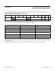
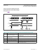
SLOTx[2:0] Setting WHICH LED IS ACTIVE LED PULSE AMPLITUDE SETTING
000 None (time slot is disabled) N/A (Off)
001 LED1 (RED) LED1_PA[7:0]
010 LED2 (IR) LED2_PA[7:0]
011 LED3 (GREEN) LED3_PA[7:0]
100 None N/A (Off)
101 LED1 (Red) PILOT_PA[7:0]
110 LED2 (IR) PILOT_PA[7:0]
111 LED3 (GREEN) PILOT_PA[7:0]
www.maximintegrated.com
Maxim Integrated
│
22
MAX30105 High-Sensitivity Optical Sensor
for Smoke Detection Applications