
Data Sheet
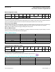

Bits 4:2: Particle-Sensing Sample Rate Control (Using 2 LEDs)
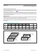
These bits define the effective sampling rate with one sample consisting of one IR pulse/conversion and one RED pulse/conversion.
The sample rate and pulse width are related in that the sample rate sets an upper bound on the pulse width time. If
the user selects a sample rate that is too high for the selected LED_PW setting, the highest possible sample rate is
programmed instead into the register.
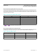
Bits 1:0: LED Pulse Width Control and ADC Resolution
These bits set the LED pulse width (the IR, Red, and Green have the same pulse width), and therefore, indirectly sets
the integration time of the ADC in each sample. The ADC resolution is directly related to the integration time.
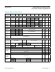
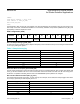
Table 6. Particle-Sensing Sample Rate Control
Table 7. LED Pulse Width Control
SR[2:0] SAMPLES PER SECOND
000 50
001 100
010 200
011 400
100 800
101 1000
110 1600
111 3200
LED_PW[1:0] PULSE WIDTH (µs) ADC RESOLUTION (bits)
00 69 (68.95) 15
01 118 (117.78) 16
10 215 (215.44) 17
11 411 (410.75) 18
See Table 11 and Table 12 for Pulse Width vs. Sample Rate information.
www.maximintegrated.com
Maxim Integrated
│
20
MAX30105 High-Sensitivity Optical Sensor
for Smoke Detection Applications