
Data Sheet
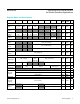
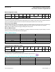

FIFO Data Contains 3 Bytes per Channel
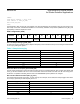
The FIFO data is left-justified, meaning that the MSB is always in the same location regardless of the ADC resolution
setting. FIFO DATA[18] – [23] are not used. Table 2 shows the structure of each triplet of bytes (containing the 18-bit
ADC data output of each channel).
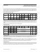
Each data sample in particle-sensing mode comprises two data triplets (3 bytes each), To read one sample, requires an
I
2
C read command for each byte. Thus, to read one sample in particle-sensing mode requires 6 I
2
C byte reads. To read
one sample with three LED channels requires 9 I
2
C byte reads. The FIFO read pointer is automatically incremented after
the first byte of each sample is read.
Write/Read Pointers
Write/Read pointers are used to control the flow of data in the FIFO. The write pointer increments every time a new
sample is added to the FIFO. The read pointer is incremented every time a sample is read from the FIFO. To reread a
sample from the FIFO, decrement its value by one and read the data register again.
The FIFO write/read pointers should be cleared (back to 0x00) upon entering particle-sensing mode, so that there is no
old data represented in the FIFO. The pointers are automatically cleared if V
DD
is power-cycled or V
DD
drops below its
UVLO voltage.
Table 2. FIFO Data (3 Bytes per Channel)
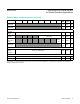
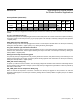
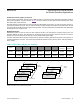
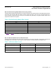
Figure 2a and 2b. Graphical Representation of the FIFO Data Register. The left shows three LEDs in multi-LED mode, and the right
shows IR and Red only in particle-sensing Mode.
BYTE 1
FIFO_
DATA[17]
FIFO_
DATA[16]
BYTE 2
FIFO_
DATA[15]
FIFO_
DATA[14]
FIFO_
DATA[13]
FIFO_
DATA[12]
FIFO_
DATA[11]
FIFO_
DATA[10]
FIFO_
DATA[9]
FIFO_
DATA[8]
BYTE 3
FIFO_
DATA[7]
FIFO_
DATA[6]
FIFO_
DATA[5]
FIFO_
DATA[4]
FIFO_
DATA[3]
FIFO_
DATA[2]
FIFO_
DATA[1]
FIFO_
DATA[0]
Sample 2: LED Channel 1
(Byte 1-3)
Sample 2: LED Channel 2
(Byte 1-3)
NEWER
SAMPLES
2(a)
Sample 2: LED Channel 3
(Byte 1-3)
Sample 1: LED Channel 3
(Byte 1-3)
Sample 1: LED Channel 1
(Byte 1-3)
Sample 1: LED Channel 2
(Byte 1-3)
2(b)
OLDER SAMPLES
Sample 2: RED Channel
(Byte 1-3)
Sample 2: IR Channel
(Byte 1-3)
NEWER
SAMPLES
2(a)
Sample 1: IR Channel
(Byte 1-3)
Sample 1: RED Channel
(Byte 1-3)
OLDER SAMPLES
www.maximintegrated.com
Maxim Integrated
│
16
MAX30105 High-Sensitivity Optical Sensor
for Smoke Detection Applications