
Data Sheet

FIFO Data Register
The circular FIFO depth is 32 and can hold up to 32 samples of data. The sample size depends on the number of LED
channels configured as active. As each channel signal is stored as a 3-byte data signal, the FIFO width can be 3 bytes,
6 bytes, 9 bytes, or 12 bytes in size.
The FIFO_DATA register in the I
2
C register map points to the next sample to be read from the FIFO. FIFO_RD_PTR
points to this sample. Reading the FIFO_DATA register does not automatically increment the I
2
C register address. Burst
reading this register reads the same address over and over. Each sample is 3 bytes of data per channel (i.e., 3 bytes for
RED, 3 bytes for IR, etc.).
The FIFO registers (0x04–0x07) can all be written and read, but in practice only the FIFO_RD_PTR register should be
written to in operation. The others are automatically incremented or filled with data by the MAX30105. When starting a new
particle-sensing
conversion, it is recommended to first clear the FIFO_WR_PTR, OVF_COUNTER, and FIFO_RD_PTR
registers to all zeroes (0x00) to ensure the FIFO is empty and in a known state. When reading the MAX30105 registers in
one burst-read I2C transaction, the register address pointer typically increments so that the next byte of data sent is from
the next register, etc. The exception to this is the FIFO data register, register 0x07. When reading this register, the address
pointer does not increment, but the FIFO_RD_PTR does. So the next byte of data sent represents the next byte of data
available in the FIFO.
Entering and exiting the proximity mode (when PROX_INT_EN = 1) clears the FIFO by setting the write and read pointers
equal to each other.
Reading from the FIFO
Normally, reading registers from the I
2
C interface autoincrements the register address pointer, so that all the registers
can be read in a burst read without an I
2
C start event. In the MAX30105, this holds true for all registers except for the
FIFO_DATA register (register 0x07).
Reading the FIFO_DATA register does not automatically increment the register address. Burst reading this register reads
data from the same address over and over. Each sample comprises multiple bytes of data, so multiple bytes should be
read from this register (in the same transaction) to get one full sample.
The other exception is 0xFF. Reading more bytes after the 0xFF register does not advance the address pointer back to
0x00, and the data read is not meaningful.
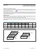
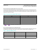
FIFO Data Structure
The data FIFO consists of a 32-sample memory bank that can store GREEN, IR, and RED ADC data. Since each sample
consists of three channels of data, there are 9 bytes of data for each sample, and therefore 288 total bytes of data can
be stored in the FIFO.
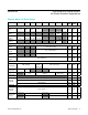
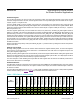
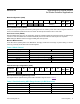
The FIFO data is left-justified as shown in Table 1; in other words, the MSB bit is always in the bit 17 data position regardless
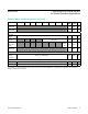
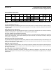
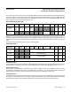
of ADC resolution setting. See Table 2 for a visual presentation of the FIFO data structure.
Table 1. FIFO Data is Left-Justified
ADC
Resolution
FIFO_DATA[17]
FIFO_DATA[16]
…
FIFO_DATA[12]
FIFO_DATA[11]
FIFO_DATA[10]
FIFO_DATA[9]
FIFO_DATA[8]
FIFO_DATA[7]
FIFO_DATA[6]
FIFO_DATA[5]
FIFO_DATA[4]
FIFO_DATA[3]
FIFO_DATA[2]
FIFO_DATA[1]
FIFO_DATA[0]
18-bit
17-bit
16-bit
15-bit
www.maximintegrated.com
Maxim Integrated
│
15
MAX30105 High-Sensitivity Optical Sensor
for Smoke Detection Applications