
Product Specifications


CY8C29466/CY8C29566
CY8C29666/CY8C29866
Document Number: 38-12013 Rev. AB Page 38 of 67
AC Electrical Characteristics
AC Chip-Level Specifications
The following table lists guaranteed maximum and minimum specifications for the voltage and temperature ranges: 4.75 V to 5.25 V
and –40 °C T
A
85 °C, or 3.0 V to 3.6 V and –40 °C T
A
85 °C, respectively. Typical parameters apply to 5 V and 3.3 V at 25 °C
and are for design guidance only.
Note See the individual user module datasheets for information on maximum frequencies for user modules.
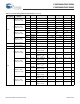
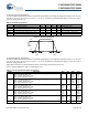
Table 29. AC Chip-Level Specifications
Symbol Description Min Typ Max Units Notes
F
IMO24
[21]
Internal main oscillator (IMO)
frequency for 24 MHz
22.8 24 25.2
[22,23]
MHz Trimmed for 5 V or 3.3 V operation using
factory trim values. See Figure 11 on page
21. SLIMO Mode = 0.
F
IMO6
IMO frequency for 6 MHz 5.5 6 6.5
[22,23]
MHz Trimmed for 5 V or 3.3 V operation using
factory trim values. See Figure 11 on page
21. SLIMO Mode = 1.
F
CPU1
CPU frequency (5 V Nominal) 0.0914 24 25.2
[22]
MHz SLIMO Mode = 0.
F
CPU2
CPU frequency (3.3 V Nominal) 0.0914 12 12.6
[23]
MHz SLIMO Mode = 0.
F
48M
Digital PSoC block frequency 0 48 50.4
[22,24]
MHz Refer to AC Digital Block Specifications on
page 43.
F
24M
Digital PSoC block frequency 0 24 25.2
[24]
MHz
F
32K1
Internal low speed oscillator
frequency
15 32 64 kHz
F
32K2
External crystal oscillator – 32.768 – kHz Accuracy is capacitor and crystal
dependent. 50% duty cycle
F
32K_U
Internal low speed oscillator (ILO)
untrimmed frequency
5 – 100 kHz After a reset and before the M8C starts to
run, the ILO is not trimmed. See the System
Resets section of the PSoC Technical
Reference Manual for details on this timing
F
PLL
PLL frequency – 23.986 – MHz A multiple (x732) of crystal frequency
T
PLLSLEW
PLL lock time 0.5 – 10 ms
T
PLLSLEWLOW
PLL lock time for low gain setting 0.5 – 50 ms
T
OS
External crystal oscillator startup to
1%
– 250 500 ms
T
OSACC
External crystal oscillator startup to
100 ppm
– 300 600 ms The crystal oscillator frequency is within
100 ppm of its final value by the end of the
T
OSACC
period. Correct operation assumes
a properly loaded 1 µW maximum drive
level 32.768 kHz crystal.
3.0 V V
DD
5.5 V, –40 °C T
A
85 °C.
T
XRST
External reset pulse width 10 – – s
DC24M 24 MHz duty cycle 40 50 60 %
DC
ILO
Internal low speed oscillator duty
cycle
20 50 80 %
Step24M 24 MHz trim step size – 50 – kHz
Fout48M 48 MHz output frequency 45.6 48.0 50.4
[22, 23]
MHz Trimmed. Using factory trim values
F
MAX
Maximum frequency of signal on
row input or row output.
– – 12.3 MHz
Notes
21. Errata: When the device is operated within 0 °C to 70 °C, the frequency tolerance is reduced to ±2.5%, but if operated at extreme temperature (below 0 °C or above
70 °C), frequency tolerance deviates from ±2.5% to ±5%. For more information, see Errata on page 61.
22. 4.75 V < V
DD
< 5.25 V.
23. 3.0 V < V
DD
< 3.6 V. See application note Adjusting PSoC
®
Trims for 3.3 V and 2.7 V Operation – AN2012 for information on trimming for operation at 3.3 V.
24. See the individual user module datasheets for information on maximum frequencies for user modules