
Product Specifications


CY8C29466/CY8C29566
CY8C29666/CY8C29866
Document Number: 38-12013 Rev. AB Page 2 of 67
More Information
Cypress provides a wealth of data at www.cypress.com to help
you to select the right PSoC device for your design, and to help
you to quickly and effectively integrate the device into your
design. For a comprehensive list of resources, see the
knowledge base article “How to Design with PSoC
®
1,
PowerPSoC
®
, and PLC – KBA88292”. Following is an
abbreviated list for PSoC 1:
■ Overview: PSoC Portfolio, PSoC Roadmap
■ Product Selectors: PSoC 1, PSoC 3, PSoC 4, PSoC 5LP
■ In addition, PSoC Designer includes a device selection tool.
■ Application notes: Cypress offers a large number of PSoC
application notes covering a broad range of topics, from basic
to advanced level. Recommended application notes for getting
started with PSoC 1 are:
❐ Getting Started with PSoC
®
1 – AN75320.
❐ PSoC
®
1 - Getting Started with GPIO – AN2094.
❐ PSoC
®
1 Analog Structure and Configuration – AN74170.
❐ PSoC
®
1 Switched Capacitor Analog Blocks – AN2041.
❐ Selecting Analog Ground and Reference – AN2219.
Note: For CY8C29X66 devices related Application note please
click here.
■ Development Kits:
❐ CY3210-PSoCEval1 supports all PSoC 1 Mixed-Signal Array
families, including automotive, except CY8C25/26xxx
devices. The kit includes an LCD module, potentiometer,
LEDs, and breadboarding space.
❐ CY3214-PSoCEvalUSB features a development board for
the CY8C24x94 PSoC device. Special features of the board
include USB and CapSense development and debugging
support.
Note: For CY8C29X66 devices related Development Kits please
click here.
The MiniProg1 and MiniProg3 devices provide interfaces for
flash programming and debug.
PSoC Designer
PSoC Designer is a free Windows-based Integrated Design
Environment (IDE). Develop your applications using a library of
pre-characterized analog and digital peripherals in a
drag-and-drop design environment. Then, customize your
design leveraging the dynamically generated API libraries of
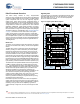
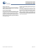
code. Figure 1 shows PSoC Designer windows. Note: This is not
the default view.
1. Global Resources – all device hardware settings.
2. Parameters – the parameters of the currently selected User
Modules.
3. Pinout – information related to device pins.
4. Chip-Level Editor – a diagram of the resources available on
the selected chip.
5. Datasheet – the datasheet for the currently selected UM
6. User Modules – all available User Modules for the selected
device.
7. Device Resource Meter – device resource usage for the
current project configuration.
8. Workspace – a tree level diagram of files associated with the
project.
9. Output – output from project build and debug operations.
Note: For detailed information on PSoC Designer, go to
PSoC
®
Designer > Help > Documentation >
Designer Specific Documents > IDE User Guide.
Figure 1. PSoC Designer Layout