
Data Sheet


PRELIMINARY
VS1063a Datasheet
10 OPERATION
10.12 SDI Tests
There are several test modes in VS1063a, which allow the user to perform memory tests, SCI
bus tests, and several different sine wave tests.
All tests are started in a similar way: VS1063a is hardware reset, SM_TESTS is set, and then a
test command is sent to the SDI bus. Each test is started by sending a 4-byte special command
sequence, followed by 4 zeros. The sequences are described below.
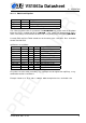
10.12.1 Sine Test
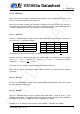
Sine test is initialized with the 8-byte sequence 0x53 0xEF 0x6E n 0 0 0 0, where n defines the
sine test to use. n is defined as follows:
n bits
Name Bits Description
F
s
Idx 7:5 Samplerate index
S 4:0 Sine skip speed
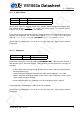
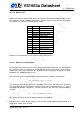
F
s
Idx F
s
F
s
Idx F
s
0 44100 Hz 4 24000 Hz
1 48000 Hz 5 16000 Hz
2 32000 Hz 6 11025 Hz
3 22050 Hz 7 12000 Hz
The frequency of the sine to be output can now be calculated from F = F
s
×
S
128
.
Example: Sine test is activated with value 126, which is 0b01111110. Breaking n to its compo-
nents, F
s
Idx = 0b011 = 3 and thus F
s
= 22050Hz. S = 0b11110 = 30, and thus the final sine
frequency F = 22050Hz ×
30
128
≈ 5168Hz.
To exit the sine test, send the sequence 0x45 0x78 0x69 0x74 0 0 0 0.
Note: Sine test signals go through the digital volume control, so it is possible to test channels
separately.
10.12.2 Pin Test
Pin test is activated with the 8-byte sequence 0x50 0xED 0x6E 0x54 0 0 0 0. This test is meant
for chip production testing only.
10.12.3 SCI Test
Sci test is initialized with the 8-byte sequence 0x53 0x70 0xEE n 0 0 0 0, where n is the
register number to test. The content of the given register is read and copied to SCI_HDAT0. If
the register to be tested is HDAT0, the result is copied to SCI_HDAT1.
Example: if n is 0, contents of SCI register 0 (SCI_MODE) is copied to SCI_HDAT0.
Version: 0.42, 2011-11-24 76