
Data Sheet


PRELIMINARY
VS1063a Datasheet
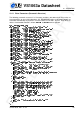
10 OPERATION
10.7.9 Encoder/Decoder Delays
This Chapter presents the absolute minimum estimated encoder/decoder total delays between
two VS1063a ICs. In addition to these numbers come all data transfer times from the transmit-
ting to the receiving unit.
The following symbols are used:
- f
s
= samplerate
- d
m
= minimum encoder/decoder delay in milliseconds
Note! Delays have been calculated for standard MP3 samplerates. Other encoders can also
encode non-standard samplerates upto 48 kHz.
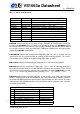
f
s
/ Hz PCM/G.711/G.722 / ms IMA / ms MP3 / ms Ogg
1
/ ms
48000 3 14 36 124
44100 3 15 40 135
32000 3 19 54 185
24000 3 25 48 125
22050 3 26 52 140
16000 3 35 72 190
12000 3 46 96 250
11025 3 49 105 270
8000 3 66 144 200
1
Numbers apply if “limited frame length” (bit 10 of register SCI_WRAMADDR) is set. If the bit
is not set, encoder/decoder delay can be upto several seconds. See Chapter 10.7.1, Encoding
Control Registers, for details on how to set the “limited frame length” bit.
10.8 Codec Mode
In the codec mode the analog to digital and digital to analog paths are separate and you can
encode and decode at the same time.
However, there are some restrictions in codec mode. The samplerate should be a XTALI/256,
XTALI/512, XTALI/1024 or XTALI/1536 (with XTALI = 12.288 MHz, possible samplerates are
thus 48000, 24000, 12000 or 8000 Hz). Also, MP3 and Ogg Vorbis formats are not available.
A RIFF WAV header is automatically generated in the encoded data, which is transferred
through SCI_HDAT1 and SCI_HDAT0 like in the normal encoding mode.
The data to be decoded is sent to SDI. The format, number of channels and samplerate are
determined from a RIFF WAV header. If you have set bit 10 of SCI_AICTRL3, the RIFF WAV
header is not expected and the format, number of channels and rate are set to the ones used
in encoding.
Note: the RIFF WAV parser used in the codec mode decoder is a simplified one.
Version: 0.42, 2011-11-24 62