IN AR Y VS1063a Datasheet VS1063a DATASHEET MP3/OGG/AAC/WMA/FLAC/ G.711/G.722 AUDIO CODEC CIRCUIT Key Features Description VS1063a is an easy-to-use, versatile encoder, decoder and codec for a multitude of audio formats.
Additional Features • • • • • • • • • • • • EarSpeaker Spatial Processing Bass & treble controls Alternatively a 5-channel equalizer AD Mixer allows monitoring A/D converter input while listening to stream PCM Mixer allows inserting a sidestream while listening to main stream Adjustable Speed Shifter Operates with a single 12. . . 13 MHz or 24. . .
VS1063a Datasheet IN AR Y CONTENTS Contents VS1063 1 Table of Contents 3 List of Figures 6 1 Disclaimer 7 2 Licenses 7 3 Definitions 8 . . . . . . 9 9 9 10 11 11 11 5 Packages and Pin Descriptions 5.1 Packages . . . . . . . . . . . . . . . . . . . . . . . . . . . . . . . . . . . . . . . 5.1.1 LQFP-48 . . . . . . . . . . . . . . . . . . . . . . . . . . . . . . . . . . 12 12 12 6 Connection Diagram, LQFP-48 15 . . . . . . . . . . . . . . . . . .
VS1063a Datasheet IN AR Y 8.1.1 8.1.2 8.1.3 8.1.4 8.2 CONTENTS Supported MP3 (MPEG layer III) Decoder Formats . . . . Supported MP2 (MPEG layer II) Decoder Formats . . . . . Supported Ogg Vorbis Decoder Formats . . . . . . . . . . Supported AAC (ISO/IEC 13818-7 and ISO/IEC 14496-3) Formats . . . . . . . . . . . . . . . . . . . . . . . . . . . . 8.1.5 Supported WMA Decoder Formats . . . . . . . . . . . . . 8.1.6 Supported FLAC Decoder Formats . . . . . . . . . . . . . 8.1.
VS1063a Datasheet IN AR Y CONTENTS . . . . . . . . . . . . . . . . . . . . . . . . . . . . . . . . . . . . . . . . . . . . . . . . . . 59 60 60 60 61 62 62 63 63 64 65 66 68 69 70 71 72 72 73 76 76 76 76 77 77 11 VS1063a Version Changes 11.1 Firmware Changes Between VS1053b and VS1063a, 2011-04-13 . . . . . . . . 78 78 12 Latest Document Version Changes 80 13 Contact Information 82 . . . . . . . . . . . . . . . . . . . . . . . . . . . . . . . . . . . . . . . . . . . . . . . . . . . . . . . . .
List of Figures Pin configuration, LQFP-48 . . . . . . . . . . . . . . . . . . . . . . . . . . . VS1063a in LQFP-48 packaging . . . . . . . . . . . . . . . . . . . . . . . . Typical connection diagram using LQFP-48 . . . . . . . . . . . . . . . . . . BSYNC signal - one byte transfer . . . . . . . . . . . . . . . . . . . . . . . . BSYNC signal - two byte transfer . . . . . . . . . . . . . . . . . . . . . . . . SCI word read . . . . . . . . . . . . . . . . . . . . . . . . . . . . . . . . . . SCI word write .
1 2 LICENSES IN AR Y VS1063a Datasheet Disclaimer This is a preliminary datasheet. All properties and figures are subject to change. This datasheet assumes that the VS1063a Patches package, available at http://www.vlsi.fi/en/support/software/vs10xxplugins.html , has been loaded and activated. Additional information is provided in two documents called VS1063a Hardware Guide, and VS1063a Programmer’s Guide. 2 Licenses MPEG Layer-3 audio coding technology licensed from Fraunhofer IIS and Thomson.
3 Definitions 3 DEFINITIONS IN AR Y VS1063a Datasheet ABR Average BitRate. Bitrate of stream may vary locally, but will stay close to a given number when averaged over a longer time. B Byte, 8 bits. b Bit. CBR Constant BitRate. Bitrate of stream will be the same for each compression block. Ki “Kibi” = 210 = 1024 (IEC 60027-2). Mi “Mebi” = 220 = 1048576 (IEC 60027-2). VBR Variable BitRate. Bitrate will vary depending on the complexity of the source material. VS_DSP VLSI Solution’s DSP core.
VS1063a Datasheet 4 4.1 Characteristics & Specifications Absolute Maximum Ratings Parameter Analog Positive Supply Digital Positive Supply I/O Positive Supply Current at Any Non-Power Pin1 Voltage at Any Digital Input Operating Temperature Storage Temperature 1 2 Symbol AVDD CVDD IOVDD Min -0.3 -0.3 -0.3 -0.3 -30 -65 Higher current can cause latch-up. Must not exceed 3.6 V Max 3.6 1.85 3.6 ±50 IOVDD+0.
VS1063a Datasheet 4.3 Analog Characteristics CHARACTERISTICS & SPECIFICATIONS IN AR Y 4 Unless otherwise noted: AVDD=3.3V, CVDD=1.8V, IOVDD=2.8V, REF=1.65V, TA=-30. . . +85◦ C, XTALI=12. . . 13MHz, Internal Clock Multiplier 3.5×. DAC tested with 1307.894 Hz full-scale output sinewave, measurement bandwidth 20. . . 20000 Hz, analog output load: LEFT to GBUF 30 Ω, RIGHT to GBUF 30 Ω. Microphone test amplitude 48 mVpp, fs =1 kHz. Line input test amplitude 1.26 V, fs =1 kHz. Symbol 2 Typ 18 0.07 0.
VS1063a Datasheet 4.4 Power Consumption CHARACTERISTICS & SPECIFICATIONS IN AR Y 4 Tested with an Ogg Vorbis 128 kbps sample and generated sine. Output at full volume. Internal clock multiplier 3.0×. TA=+25◦ C. Parameter Power Supply Consumption AVDD, Reset Power Supply Consumption CVDD = 1.8V, Reset Power Supply Consumption AVDD, sine test, 30 Ω + GBUF Power Supply Consumption CVDD = 1.
VS1063a Datasheet 5 PACKAGES AND PIN DESCRIPTIONS IN AR Y 5 Packages and Pin Descriptions 5.1 Packages LPQFP-48 is a lead (Pb) free and also RoHS compliant package. RoHS is a short name of Directive 2002/95/EC on the restriction of the use of certain hazardous substances in electrical and electronic equipment. 5.1.1 LQFP-48 48 IM 1 Figure 1: Pin configuration, LQFP-48 PR EL LQFP-48 package dimensions are at http://www.vlsi.fi/ . Figure 2: VS1063a in LQFP-48 packaging Version: 0.
VS1063a Datasheet Pin Type AI AI DI DGND CPWR IOPWR CPWR DO DIO DIO DIO DIO Function 13 14 15 16 17 18 19 20 21 22 23 24 25 26 27 28 29 30 31 32 33 DI IOPWR DO DGND AO AI IOPWR DGND DGND DGND DI CPWR DIO DI DO DI DI DO3 CPWR DI DIO Data chip select / byte sync I/O power supply For testing only (Clock VCO output) Core & I/O ground Crystal output Crystal input I/O power supply Core & I/O ground Core & I/O ground Core & I/O ground Chip select input (active low) Core power supply General purpose IO 5 / I2S_
VS1063a Datasheet 1 PACKAGES AND PIN DESCRIPTIONS IN AR Y 5 First pin function is active in New Mode, latter in Compatibility Mode. 2 Unless pull-down resistor is used, SPI Boot, followed by I2C Boot, is tried. See Chapters 10.9, SPI Boot, and 10.10, I2C Boot, for details. 3 If I2S_CF_ENA is ’0’ the pins are used for GPIO. See VS1063a Hardware Guide’s Chapter I2S DAC Interface for details.
VS1063a Datasheet Connection Diagram, LQFP-48 EL IM 6 CONNECTION DIAGRAM, LQFP-48 IN AR Y 6 PR Figure 3: Typical connection diagram using LQFP-48 Figure 3 shows a typical connection diagram for VS1063. Figure Note 1: Connect either Microphone In or Line In, but not both at the same time. Note: This connection assumes SM_SDINEW is active (see Chapter 9.8.1). If also SM_SDISHARE is used, xDCS should be tied high (see Chapter 7.2.1). Version: 0.
VS1063a Datasheet CONNECTION DIAGRAM, LQFP-48 IN AR Y 6 The common buffer GBUF can be used for common voltage (1.23 V) for earphones. This will eliminate the need for large isolation capacitors on line outputs, and thus the audio output pins from VS1063a may be connected directly to the earphone connector. GBUF must NOT be connected to ground under any circumstances. If GBUF is not used, LEFT and RIGHT must be provided with coupling capacitors.
7 SPI Buses 7.1 General 7 SPI BUSES IN AR Y VS1063a Datasheet The SPI Bus - that was originally used in some Motorola devices - has been used for both VS1063a’s Serial Data Interface SDI (Chapters 7.4 and 9.6) and Serial Control Interface SCI (Chapters 7.5 and 9.7). 7.2 SPI Bus Pin Descriptions 7.2.1 VS10xx Native Modes (New Mode) These modes are active on VS1063a when SM_SDINEW is set to 1 (default at startup).
SDI Pin - SCI Pin XCS BSYNC DCLK SCK SDATA - SI SO 7.3 7 SPI BUSES IN AR Y VS1063a Datasheet Description Active low chip select input. A high level forces the serial interface into standby mode, ending the current operation. A high level also forces serial output (SO) to high impedance state. SDI data is synchronized with a rising edge of BSYNC. Serial clock input. The serial clock is also used internally as the master clock for the register interface. SCK can be gated or continuous.
7.4 7.4.1 7 SPI BUSES IN AR Y VS1063a Datasheet Serial Protocol for Serial Data Interface (SDI) General The serial data interface operates in slave mode so DCLK signal must be generated by an external circuit. Data (SDATA signal) can be clocked in at either the rising or falling edge of DCLK (Chapter 9.8). VS1063a assumes its data input to be byte-sychronized. SDI bytes may be transmitted either MSb or LSb first, depending of register SCI_MODE bit SM_SDIORD (Chapter 9.8.1).
7.4.3 7 SPI BUSES IN AR Y VS1063a Datasheet SDI in VS1001 Compatibility Mode (deprecated) BSYNC SDATA D7 D6 D5 DCLK D4 D3 D2 D1 D0 Figure 4: BSYNC signal - one byte transfer When VS1063a is running in VS1001 compatibility mode, a BSYNC signal must be generated to ensure correct bit-alignment of the input bitstream.
7.5 7.5.1 7 SPI BUSES IN AR Y VS1063a Datasheet Serial Protocol for Serial Command Interface (SCI) General The serial bus protocol for the Serial Command Interface SCI (Chapter 9.7) consists of an instruction byte, address byte and one 16-bit data word. Each read or write operation can read or write a single register. Data bits are read at the rising edge, so the user should update data at the falling edge. Bytes are always send MSb first.
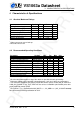
VS1063a Datasheet SCI Write XCS 0 1 2 3 4 5 6 7 8 9 10 11 12 13 14 15 16 17 0 0 0 0 0 0 1 0 0 0 0 SCK 3 SI instruction (write) SO 0 0 0 0 0 0 2 1 0 0 0 0 30 31 15 14 0 1 0 X 0 data out address 0 SPI BUSES IN AR Y 7.5.3 7 0 0 0 0 0 0 0 0 X 0 execution DREQ Figure 7: SCI word write VS1063a registers are written from using the following sequence, as shown in Figure 7. First, XCS line is pulled low to select the device.
VS1063a Datasheet SPI BUSES IN AR Y 7 XCS up after sending the last bit of a data word, the next data word is sent immediately. After the last data word, XCS is driven high as with a single word write. After the last bit of a word has been sent, DREQ is driven low for the duration of the register update, marked “execution” in the figure. The time varies depending on the register and its contents (see table in Chapter 9.8 for details).
VS1063a Datasheet 7.7.1 SPI BUSES IN AR Y 7.7 7 SPI Examples with SM_SDINEW and SM_SDISHARED set Two SCI Writes SCI Write 1 SCI Write 2 XCS 0 1 2 3 30 SCK 1 SI 0 0 0 32 31 0 X 0 33 0 61 62 63 2 1 0 X 0 DREQ up before finishing next SCI write DREQ Figure 10: Two SCI operations 7.7.2 Two SDI Bytes IM Figure 10 shows two consecutive SCI operations. Note that xCS must be raised to inactive state between the writes. Also DREQ must be respected as shown in the figure.
VS1063a Datasheet SPI BUSES IN AR Y 7.7.3 7 SCI Operation in Middle of Two SDI Bytes SDI Byte XCS 0 7 1 8 SCK 7 6 5 1 9 39 0 0 SI SDI Byte SCI Operation 40 41 7 6 5 46 47 1 0 X 0 DREQ high before end of next transfer DREQ Figure 12: Two SDI bytes separated by an SCI operation PR EL IM Figure 12 shows how an SCI operation is embedded in between SDI operations. xCS edges are used to synchronize both SDI and SCI. Remember to respect DREQ as shown in the figure.
VS1063a Datasheet 8 Supported Audio Formats 8.1 Supported Audio Decoders Mark + - 8.1.1 SUPPORTED AUDIO FORMATS IN AR Y 8 Conventions Description Format is supported Format exists but is not supported Format doesn’t exist Supported MP3 (MPEG layer III) Decoder Formats The VS1063 MP3 decoder is full-accuracy compliant. MPEG 1.01 : Samplerate / Hz 48000 44100 32000 32 + + + 40 + + + 8 + + + 16 + + + 8 + + + 16 + + + 48 + + + 56 + + + 64 + + + Samplerate / Hz 24000 22050 16000 MPEG 2.
VS1063a Datasheet MPEG 2.0: Samplerate / Hz 24000 22050 16000 8.1.3 8 + + + 16 + + + 24 + + + 32 + + + 40 + + + SUPPORTED AUDIO FORMATS IN AR Y 8 48 + + + Bitrate / kbit/s 56 64 80 + + + + + + + + + 96 + + + 112 + + + 128 + + + 144 + + + 160 + + + Supported Ogg Vorbis Decoder Formats Parameter Channels Window size Samplerate Bitrate Min 1 64 1 0 Max 2 4096 48000 500 Unit samples Hz kbit/sec Of the two Ogg Vorbis floors, only floor 1 is supported.
VS1063a Datasheet SUPPORTED AUDIO FORMATS IN AR Y 8 clock. PS and SBR operation is automatically switched off if the internal clock is too slow for correct decoding. Generally HE-AAC v2 files need 4.5× clock to decode both SBR and PS content. This is why 3.5× + 1.0× clock is the recommended default. For AAC the streaming ADTS format is recommended. This format allows easy rewind and fast forward because resynchronization is easily possible. In addition to ADTS (.aac), MPEG2 ADIF (.
VS1063a Datasheet 8.1.5 SUPPORTED AUDIO FORMATS IN AR Y 8 Supported WMA Decoder Formats Windows Media Audio codec versions 2, 7, 8, and 9 are supported. All WMA profiles (L1, L2, and L3) are supported. Previously streams were separated into Classes 1, 2a, 2b, and 3. The decoder has passed Microsoft’s conformance testing program. Windows Media Audio Professional and Windows Media Audio Voice are different codecs and are not supported. WMA 4.0 / 4.
VS1063a Datasheet 8.1.6 SUPPORTED AUDIO FORMATS IN AR Y 8 Supported FLAC Decoder Formats The FLAC decoder provides the highest quality by providing lossless audio decompression. Upto 48 kHz and 24-bit FLAC files with upto two channels are supported. Because of the high data rate, the requirements for data transfer are much higher than for lossy codecs.
VS1063a Datasheet 8.2 8.2.1 SUPPORTED AUDIO FORMATS IN AR Y 8 Supported Audio Encoding Formats Supported MP3 (MPEG layer III) Encoding Formats VS1063a supports all MP3 samplerates and bitrates, in stereo and mono, both with constant bit-rate (CBR) or variable bitrate (VBR). The following tables apply to both formats. Symbol ++ + x v < - Conventions Description Format is supported and recommended for this channel configuration and bitrate. Format is supported.
VS1063a Datasheet 8.2.2 SUPPORTED AUDIO FORMATS IN AR Y 8 Supported Ogg Vorbis Encoding Formats The Ogg Vorbis Encoder supports encoding in mono and stereo, with any samplerate between 1 and 48000 Hz, and with different quality settings. Ogg Vorbis is always encoded using variable bitrate (VBR). Some example setting profiles are provided below. Note, however, that the encoder is not limited to these configurations. The “Voice” profiles are intended for speech applications.
VS1063a Datasheet 9 9.1 Functional Description Main Features FUNCTIONAL DESCRIPTION IN AR Y 9 VS1063a is based on a proprietary digital signal processor, VS_DSP. It contains all the code and data memory needed for Ogg Vorbis, MP3, AAC, WMA, FLAC and WAV PCM + ADPCM audio decoding together with serial interfaces, a multirate stereo audio DAC and analog output amplifiers and filters. Also MP3, OGG, PCM, ADPCM, µ-law, A-law and G.
VS1063a Datasheet 9.
VS1063a Datasheet FUNCTIONAL DESCRIPTION IN AR Y 9 After that the data is fed to the Audio FIFO. The size of the audio FIFO is 2048 stereo (2×16-bit) samples, or 8 KiB. Now decoded and processed audio is sent to a samplerate converter, where volume control is applied. After this step it is combined with an optional sidestream which may be either PCM samples coming through the SCI bus or analog data from the line/mic input.
VS1063a Datasheet 9.
VS1063a Datasheet 9.5 FUNCTIONAL DESCRIPTION IN AR Y 9 EarSpeaker Spatial Processing While listening to headphones the sound has a tendency to be localized inside the head. The sound field becomes flat and lacking the sensation of dimensions. This is an unnatural, awkward and sometimes even disturbing situation. This phenomenon is often referred in literature as ‘lateralization’, meaning ’in-the-head’ localization. Long-term listening to lateralized sound may lead to listening fatigue.
VS1063a Datasheet FUNCTIONAL DESCRIPTION IN AR Y 9 EarSpeaker processing can be adjusted using parametric_x.earSpeakerLevel. Different levels simulate a little different type of acoustical situation, suiting different personal preferences and types of recording. • 0: Best option when listening through loudspeakers or if the audio to be played contains binaural preprocessing. • 12000: Suited for listening to normal musical scores with headphones, very subtle.
VS1063a Datasheet 9.8 FUNCTIONAL DESCRIPTION IN AR Y 9 SCI Registers VS1063a sets DREQ low when it detects an SCI operation (this delay is 16 to 40 CLKI cycles depending on whether an interrupt service routine is active) and restores it when it has processed the operation. The duration depends on the operation. If DREQ is low when an SCI operation is performed, it also stays low after SCI operation processing.
VS1063a Datasheet 9.8.1 FUNCTIONAL DESCRIPTION IN AR Y 9 SCI_MODE (RW) SCI_MODE is used to control the operation of VS1063a and defaults to 0x0800 (SM_SDINEW set). Note: “Mode” in the following table tells if that bit is a hardware (HW) or software (SW) control.
VS1063a Datasheet FUNCTIONAL DESCRIPTION IN AR Y 9 honouring DREQ. When SM_CANCEL is detected by a codec, it will stop decoding and return to the main loop. The stream buffer content is discarded and the SM_CANCEL bit cleared. SCI_HDAT1 will also be cleared. See Chapter 10.5.2 for details. If SM_TESTS is set, SDI tests are allowed. For more details on SDI tests, look at Chapter 10.12. SM_DACT defines the active edge of data clock for SDI.
VS1063a Datasheet 9.8.2 SCI_STATUS (RW) FUNCTIONAL DESCRIPTION IN AR Y 9 SCI_STATUS contains information on the current status of VS1063a. It also controls some low-level things that the user does not usually have to care about. Note: “Mode” in the following table tells if that bit is a hardware (HW) or software (SW) control.
VS1063a Datasheet 9.8.3 SCI_BASS (RW) Name ST_AMPLITUDE ST_FREQLIMIT SB_AMPLITUDE SB_FREQLIMIT Bits 15:12 11:8 7:4 3:0 FUNCTIONAL DESCRIPTION IN AR Y 9 Description Treble Control in 1.5 dB steps (-8. . . 7, 0 = off) Lower limit frequency in 1000 Hz steps (1. . . 15) Bass Enhancement in 1 dB steps (0. . . 15, 0 = off) Lower limit frequency in 10 Hz steps (2. . .
VS1063a Datasheet 9.8.4 SCI_CLOCKF (RW) FUNCTIONAL DESCRIPTION IN AR Y 9 The operation of SCI_CLOCKF has changed slightly in VS1063a compared to VS1003 and VS1033. Multiplier 1.5× and addition 0.5× have been removed to allow higher clocks to be configured. Name SC_MULT SC_ADD SC_FREQ SCI_CLOCKF bits Bits Description 15:13 Clock multiplier 12:11 Allowed multiplier addition 10: 0 Clock frequency SC_MULT activates the built-in clock multiplier. This will multiply XTALI to create a higher CLKI.
VS1063a Datasheet 9.8.5 SCI_DECODE_TIME (RW) FUNCTIONAL DESCRIPTION IN AR Y 9 When decoding correct data, current decoded time is shown in this register in full seconds. The user may change the value of this register. In that case the new value should be written twice to make absolutely certain that the change is not overwritten by the firmware. A write to SCI_DECODE_TIME also resets the bitRatePer100 calculation. SCI_DECODE_TIME is reset at every hardware and software reset.
VS1063a Datasheet 9.8.9 SCI_HDAT0 and SCI_HDAT1 (R) FUNCTIONAL DESCRIPTION IN AR Y 9 For WAV files, SCI_HDAT1 contains 0x7665 (“ve”). SCI_HDAT0 contains the data rate measured in bytes per second for all supported RIFF WAVE formats. To get the bitrate of the file, multiply the value by 8. Note: if bitrate is over 524280 bit/s, SCI_HDAT1 value saturates to 65535. For AAC ADTS streams, SCI_HDAT1 contains 0x4154 (“AT”). For AAC ADIF files, SCI_HDAT1 contains 0x4144 (“AD”). For AAC .mp4 / .
VS1063a Datasheet FUNCTIONAL DESCRIPTION IN AR Y 9 For MP3 files, SCI_HDAT1 is between 0xFFE0 and 0xFFFF.
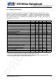
VS1063a Datasheet “bitrate” 15 14 13 12 11 10 9 8 7 6 5 4 3 2 1 0 FUNCTIONAL DESCRIPTION IN AR Y 9 Layer II ID=3 ID=0,1,2 kbit/s forbidden forbidden 384 160 320 144 256 128 224 112 192 96 160 80 128 64 112 56 96 48 80 40 64 32 56 24 48 16 32 8 - Layer III ID=3 ID=0,1,2 kbit/s forbidden forbidden 320 160 256 144 224 128 192 112 160 96 128 80 112 64 96 56 80 48 64 40 56 32 48 24 40 16 32 8 - IM The average data rate in bytes per second can be read from memory, see the bitRatePer100 extra parameter.
VS1063a Datasheet 9.8.10 SCI_AIADDR (RW) FUNCTIONAL DESCRIPTION IN AR Y 9 SCI_AIADDR defines the start address of the application/plugin code that has been uploaded earlier with SCI_WRAMADDR and SCI_WRAM registers. If no application code is used, this register should not be written to, or it should be written zero. Note: Reading SCI_AIADDR is not recommended. For more details on how to write user applications and plugins, see VS1063 Programmer’s Guide. 9.8.
10 10.1 10 OPERATION IN AR Y VS1063a Datasheet Operation Clocking VS1063a operates on a single, nominally 12.288 MHz fundamental frequency master clock. This clock can be generated by external circuitry (connected to pin XTALI) or by the internal clock crystal interface (pins XTALI and XTALO). This clock is used by the analog parts and determines the highest available samplerate. With 12.288 MHz clock all samplerates upto 48000 Hz are available. VS1063a can also use 24. . .
10.3 Software Reset 10 OPERATION IN AR Y VS1063a Datasheet In some cases the decoder software has to be reset. This is done by activating bit SM_RESET in register SCI_MODE (Chapter 9.8.1). Then wait for at least 2 µs, then look at DREQ. DREQ will stay down for about 22000 clock cycles, which means an approximate 1.8 ms delay if VS1063a is run at 12.288 MHz. When DREQ goes high, you may continue playback as usual.
10.5.1 Playing a Whole File This is the default playback mode. 10 OPERATION IN AR Y VS1063a Datasheet 1. Send an audio file to VS1063a. 2. Read extra parameter value endFillByte (Chapter 10.11). 3. Send at least 2052 bytes of endFillByte[7:0]. For FLAC you should send 12288 endFillBytes when ending a file. 4. Set SCI_MODE bit SM_CANCEL. 5. Send at least 32 bytes of endFillByte[7:0]. 6. Read SCI_MODE. If SM_CANCEL is still set, go to 5.
10 OPERATION IN AR Y VS1063a Datasheet To estimate whether or not your microcontroller can feed enough data to VS1063a in fast play mode, see contents of extra parameter value bitRatePer100 (Chapter 10.11). Note that bitRatePer100 contains the data speed of the file played back at nominal speed even when fast play is active. Note: Play speed is not reset when song is changed. 10.5.
10.6 Feeding PCM Data 10 OPERATION IN AR Y VS1063a Datasheet VS1063a can be used as a PCM decoder by sending a WAV file header, followed by PCM data. If the length sent in the WAV header is 0xFFFFFFFF, VS1063a will stay in PCM mode indefinitely (or until SM_CANCEL has been set). 8-bit linear and 16-bit linear audio is supported in mono or stereo.
10.7 Audio Encoding 10 OPERATION IN AR Y VS1063a Datasheet This chapter explains how to use the encoding and codec modes of VS1063a. VS1063 has a stereo ADC, thus also two-channel (separate AGC, if AGC enabled) and stereo (common AGC, if AGC enabled) modes are available. Mono encoding can select either left or right channel, or a mono down-mix of the left and right channels. The left channel is either MIC or LINE1 depending on the SCI_MODE register, the right channel is LINE2.
10 OPERATION IN AR Y VS1063a Datasheet SCI_WRAMADDR sets the quality / bit rate selection for Ogg Vorbis and MP3 encoding. For WAV formats this setting is not used. Use value 0xe080 for constant bitrate of 128 kbps. Note that WRAMADDR is read at encoder startup, so modifying it later does not change the settings.
10.7.2 The Encoding Procedure 10 OPERATION IN AR Y VS1063a Datasheet The encoding procedure from start to finish goes as follows: 1. Pre-initialization; Setup system: • Load the VS1063a Patches package, available at http://www.vlsi.fi/en/support/software/vs10xxplugins.html . Note that the package is required for conforming MP3 bitstreams: without it recording quality will be significantly lower and the bitstream may have errors. 2.
10 OPERATION IN AR Y VS1063a Datasheet Example of Encoding initialization including loading VS1063a Patches: // First command line loads VS1063a Patches. The patch package can be // loaded from http://www.vlsi.fi/en/support/software/vs10xxplugins.html // This package is required for best MP3 quality and correct monitoring. LoadUserCode(vs1063apatch); WriteVS10xxRegister(SCI_AICTRL0, 48000U); // 48 kHz WriteVS10xxRegister(SCI_AICTRL1, 1024U); // Manual gain at 1.
10.7.4 10 OPERATION IN AR Y VS1063a Datasheet File Headers VS1063 automatically creates a suitable header for the selected encoding mode. If you have selected MP3 or Ogg Vorbis, the headers will be in those formats, otherwise you get a RIFF WAV header with the correct samplerate, number of channels, and other information. (If you have set bit 10 of SCI_AICTRL3, the RIFF WAV header is not generated.) When you finish encoding you have to fix the RIFF size and data size fields.
10.7.5 Playing Encoded Data 10 OPERATION IN AR Y VS1063a Datasheet In order to play back your encoding, all you need to do is to provide the file through SDI as you would with any audio file. 10.7.6 Encoder Samplerate Considerations For encoder samplerates to work accurately, it is recommended to load and run the VS1063a Patches package. It is is available at http://www.vlsi.fi/en/support/software/vs10xxplugins.html . When the VS1063a Patches package, v1.
10.7.8 10 OPERATION IN AR Y VS1063a Datasheet Encoder-Specific Considerations MP3 (format 5) The MP3 encoder supports all bitrates and samplerates of the MP3 format, both in mono and stereo. For details of supported and recommended modes, see Chapter 8.2.1. Notice particularly that only the MP3 official samplerates are supported (8000, 11025, 12000, 16000, 22050, 24000, 32000, 44100 and 48000 Hz). If you try to start MP3 encoding with any other samplerate, the encoder will silently fail.
10.7.9 Encoder/Decoder Delays 10 OPERATION IN AR Y VS1063a Datasheet This Chapter presents the absolute minimum estimated encoder/decoder total delays between two VS1063a ICs. In addition to these numbers come all data transfer times from the transmitting to the receiving unit. The following symbols are used: - fs = samplerate - dm = minimum encoder/decoder delay in milliseconds Note! Delays have been calculated for standard MP3 samplerates.
10.9 SPI Boot 10 OPERATION IN AR Y VS1063a Datasheet If GPIO0 is set with a pull-up resistor to 1 at boot time, VS1063a tries to boot from external SPI memory. SPI boot redefines the following pins: Normal Mode GPIO0 GPIO1 DREQ GPIO2 SPI Boot Mode xCS CLK MOSI MISO The memory has to be an SPI Bus Serial EEPROM with 16-bit or 24-bit addresses. The serial speed used by VS1063a is 245 kHz with the nominal 12.288 MHz clock. The first three bytes in the memory have to be 0x50, 0x26, 0x48. 10.
10.11 10 OPERATION IN AR Y VS1063a Datasheet Extra Parameters (Parametric Structure) The following parametric structure is in X memory at address 0x1e00 and can be used to set extra parameters or get useful information. SCI_WRAMADDR addresses 0xc0c0 to 0xc0ff are translated automatically to parametric structure addresses 0x1e00. . . 0x1e3f. Also, when an address from 0xc0c0 to 0xc0ff is written, sdiFree and audioFill are updated.
10.11.1 chipID, version, config1 Parameter chipID version config1 Address 0x1e00-01 0x1e02 0x1e03 10 OPERATION IN AR Y VS1063a Datasheet Usage Fuse-programmed unique ID (cosmetic copy of the fuses) Structure version – 0x0004 Miscellaneous configuration The fuse-programmed ID is read at startup and copied into the chipID field. If not available, the value will be all zeros. The version field can be used to determine the layout of the rest of the structure.
10.11.2 Player Configurations Parameter playSpeed bitRatePer100 endFillByte rateTune playMode sampleCounter sdiFree audioFill latestSOF positionMsec resync Address 0x1e04 0x1e05 0x1e06 0x1e07:1e08 0x1e09 0x1e0a:1e0b 0x1e1f 0x1e20 0x1e25:1e26 0x1e27:1e28 0x1e29 10 OPERATION IN AR Y VS1063a Datasheet Usage 0,1 = normal speed, 2 = double, 3 = three times etc.
10 OPERATION IN AR Y VS1063a Datasheet sampleCounter advances for each played sample and is initialized by Ogg Vorbis decoding. sdiFree and audioFill can be used to monitor and control the playback delay in special applications. sdiFree and audioFill are updated when WRAMADDR is written with values from 0xc0c0 to 0xc0ff. These translate to parametric stucture addresses 0x1e00. . . 0x1e3f automatically. So, write 0xc0df to WRAMADDR, and then read WRAM twice to get both sdiFree and audioFill.
10 OPERATION IN AR Y VS1063a Datasheet Notice that reading two-word variables through the SCI_WRAMADDR and SCI_WRAM interface is only partly atomic. In VS1063 a write to SCI_WRAMADDR reads ahead two words that it provides to SCI_WRAM, so the two halfs of a long variable are sampled together. But as the write to the variable may not be protected from interrupts, the SCI interrupt may occur between the update of the low and high parts of the variable. It is quite improbable though.
10.11.4 AD Mixer Parameter playMode adMixerGain adMixerConfig #define #define #define #define #define #define #define #define #define #define Address 0x1e09 0x1e0d 0x1e0e 10 OPERATION IN AR Y VS1063a Datasheet Usage bit 3: AD Mixer enable AD mixer attenuation in 3dB steps -3. . .
10.11.5 PCM Mixer Parameter playMode pcmMixerRate pcmMixerFree pcmMixerVol Address 0x1e09 0x1e0f 0x1e10 0x1e11 10 OPERATION IN AR Y VS1063a Datasheet Usage bit 4: PCM Mixer enable PCM mixer samplerate PCM mixer FIFO free state PCM mixer volume 0. . . 191 (-0.5 dB steps) The PCM Mixer allows a mono 16-bit linear PCM stream be played back during any audio format playback.
10.11.6 EQ5 5-band Equalizer Parameter playMode eq5Params eq5Update Address 0x1e09 0x1e12/1b 0x1e1c 10 OPERATION IN AR Y VS1063a Datasheet Usage bit 5: EQ5 enable Frequency/gain pairs Indicator that settings have been changed The 5-band equalizer takes its parameters from eq5Params array, which needs to be written before the EQ5 is enabled from bit 5 of playMode. If the settings are changed while EQ5 is active, new settings can be forced to be taken into use by writing a non-zero value to eq5Update.
10.11.7 Speed Shifter Parameter playMode speedShifter Address 0x1e09 0x1e1d 10 OPERATION IN AR Y VS1063a Datasheet Usage bit 6: SpeedShifter enable Speed shifter speed, 0x4000 = 1.0x Speed shifter allows the playback tempo to be changed without changing the playback pitch. ter The playback tempo is speedShif , i.e. 16384 is the normal speed. The minimum speed is 16384 0.68x (11141) and maximum speed 1.64x (26869).
10.11.9 Other Parameters WMA Parameter curPacketSize packetSize Address 0x1e2a/2b 0x1e2c/2d 10 OPERATION IN AR Y VS1063a Datasheet Usage The size of the packet being processed The packet size in ASF header The ASF header packet size is available in packetSize. With this information and a packet start offset from latestSOF you can parse the packet headers and skip packets in ASF files.
Bit 0 1 2 3 10 OPERATION IN AR Y VS1063a Datasheet Usage SBR present upsampling active PS present PS active Bits 7 to 4 in config1 can be used to control the SBR and PS decoding. Bits 5 and 4 select SBR mode and bits 7 and 6 select PS mode. These configuration bits are useful if your AAC license does not cover SBR and/or PS.
Ogg Vorbis Parameter gain Address 0x1e2a 10 OPERATION IN AR Y VS1063a Datasheet Usage Preferred replay-gain offset Ogg Vorbis decoding supports Replay Gain technology. The Replay Gain technology is used to automatically give all songs a matching volume so that the user does not need to adjust the volume setting between songs. If the Ogg Vorbis decoder finds a Replay Gain tag in the song header, the tag is parsed and the decoded gain setting can be found from the gain parameter.
10.12 10 OPERATION IN AR Y VS1063a Datasheet SDI Tests There are several test modes in VS1063a, which allow the user to perform memory tests, SCI bus tests, and several different sine wave tests. All tests are started in a similar way: VS1063a is hardware reset, SM_TESTS is set, and then a test command is sent to the SDI bus. Each test is started by sending a 4-byte special command sequence, followed by 4 zeros. The sequences are described below. 10.12.
10.12.4 Memory Test 10 OPERATION IN AR Y VS1063a Datasheet Memory test mode is initialized with the 8-byte sequence 0x4D 0xEA 0x6D 0x54 0 0 0 0. After this sequence, wait for 1100000 clock cycles.
VS1063a Datasheet 11 VS1063A VERSION CHANGES IN AR Y 11 VS1063a Version Changes This chapter describes the lastest and most important changes done to VS1063a 11.1 Firmware Changes Between VS1053b and VS1063a, 2011-04-13 VS1063a is a pin-compatible firmware upgrade to the VS1053b. Completely new or major changes: • Added MP3, Ogg Vorbis, µ-law, A-law and G.722 encoding. • Added codec mode. • Removed MIDI and MPEG layer I (MP1) decoders. • Layers II and III: new, more robust and accurate decoding.
VS1063a Datasheet Minor changes and bug fixes: VS1063A VERSION CHANGES IN AR Y 11 • IROM4 switched off and DO_NOT_JUMP cleared in software reset also. • Handles SM_CANCEL also for mp3 (clears stream buffer). • Fixed a problem when the first ’OggS’ in Ogg Vorbis file was spanning the end and beginning of stream buffer. • AAC feature drop works in non-implicit upsample mode, and was also otherwise improved. • Default AAC decoding mode is non-implicit upsample, i.e.
VS1063a Datasheet 12 LATEST DOCUMENT VERSION CHANGES IN AR Y 12 Latest Document Version Changes This chapter describes the most important changes to this document. Version 0.42, 2011-11-24 • Updated Chapter 10.7.6, Samplerate Considerations (page 60), to reflect enhancements caused by the latest VS1063a Patches v1.2 package. • Added text to Chapter 1, Disclaimer, to inform that this document is only valid when the latest VS1063a Patches package has been loaded and activated. Version 0.
VS1063a Datasheet Version 0.20, 2011-04-14 LATEST DOCUMENT VERSION CHANGES IN AR Y 12 • First public release of the complete datasheet. • Parts of datasheet split into VS1063a Hardware Guide and VS1063a Programmer’s Guide. These guides will be published in May 2011. Version 0.10, 2011-01-17 PR EL IM • First two pages released on VLSI’s web pages. Version: 0.
VS1063a Datasheet 13 CONTACT INFORMATION IN AR Y 13 Contact Information VLSI Solution Oy Entrance G, 2nd floor Hermiankatu 8 FI-33720 Tampere FINLAND PR EL IM Fax: +358-3-3140-8288 Phone: +358-3-3140-8200 Email: sales@vlsi.fi URL: http://www.vlsi.fi/ Version: 0.