
Guide

Once your BD-LLC is soldered up, it’s time to hook it up. Your hookup will probably vary depending on
which communication interface you’re using. Below we’ll show how to hook the level converter for three of
the most common communication protocols.
Using the BD-LLC for Serial
Although you won’t be taking advantage of the BD-LCC’s bi-directional abilities, it’s perfectly fine to use
the board to shift serial communication. Serial usually requires two signal wires – RX
(receive) and TX
(transmit) – which both have a defined direction. These signals can be passed through any of the four
channels on the BD-LLC.
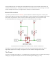
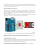
Let’s say, for example, you want to hookup an Electric Imp Breakout Board (which has a 3.6V maximum
input voltage) to an Arduino Uno via their UARTs. Here’s one possible hook up:
Please note that the Arduino and the Electric both have their own power supplies in this example.
Make sure LV
is powered at 3.3V, and HV
is at 5V. Double-check that the channels match up, and
a-shifting you will go! You’ve even got two extra channels to shift as you please.
Using the BD-LLC for SPI
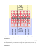
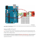
The BD-LLC’s four channels are a perfect match for most SPI communications. SPI usually requires four
wires: MOSI (master out, slave in), MISO (master in, slave out), SCLK (serial clock), and CS (chip select).
These four wires can each be routed through a channel on the BD-LLC.
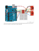
For example, if you wanted to connect an Arduino to an ADXL345 Breakout Board, which has an
operating range of 2.0-3.6V, here’s how the BD-LLC could be spliced in: