
Guide
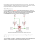
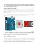

There are four separate data channels on the BD-LLC, each capable of shifting data to and from high and
low voltages. These pins are labeled HV1
, LV1
, HV2
, LV2
, HV3
, LV3
, HV4
, and LV4
. The number at the
end of each label designates the channel of the pin, and the HV
or LV
prefix determines whether it’s on
the high or low side of the channel.
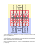
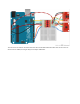
A low-voltage signal sent in to LV1
, for example, will be shifted up to the higher voltage and sent out HV1
.
Something sent in HV3
will be shifted down and sent out of LV3
. Use as many of these channels as your
project requires. You don’t have to use every single one.
Keep in mind that these level shifters are purely digital. They can’t map an analog voltage from one max
voltage to another.
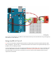
Hookup Examples
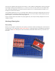
Assembly
Before you can plug the converter into your system, you’ll need to solder something into it. There are a lot
of options here. You could solder straight male headers in, and plug it right into a breadboard. Or perhaps
you want to solder wires directly into it. Pick an assembly method that melds with how you intend to use
the board.