
Guide

In this tutorial we’ll take an in-depth look at the Bi-Directional Logic Level Converter. We’ll examine the
schematic and board layout – explaining what each pin on the board does. At the end we’ll go over some
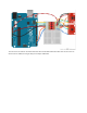
hookup examples to show how you might hook the board up for various interfaces.
Board Overview
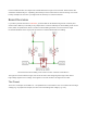
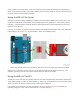
If you take a peek at the board’s schematic, you’d find that the bi-directional logic level converter (let’s
shorten that to BD-LLC) is actually a very simple device. There is basically one level-shifting circuit on the
board, which is repeated four times to create four level-shifting channels. The circuit uses a single
N-channel MOSFET and a couple pull-up resistors to realize bidirectional level shifting.
The bi-directional level-shifting circuit used on all four channels of the BD-LLC.
Through some semiconductor magic, this circuit can shift a low voltage signal to high and/or
shift a
high-voltage signal to a low voltage. A 0V signal on one end remains a 0V signal on the other.
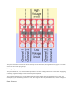
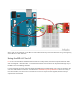
The Pinout
There are 12 total pins on the BD-LLC – two parallel rows of six headers. One row contains all of the high
voltage (e.g. 5V) inputs and outputs, the other row has all things low voltage (e.g. 3.3V).