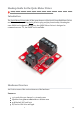
Hookup Guide for the Qwiic Motor Driver learn.sparkfun.com/tutorials/hookup-guide-for-the-qwiic-motor-driver/all Introduction The Qwiic Motor Driver takes all the great features of the Serial Controlled Motor Driver and mini-sizes them, adding Qwiic ports for plug and play functionality. Boasting the same PSOC and 2-channel motor ports, the QWIIC Motor Driver is designed to communicate over I2C, but UART is also available. Hardware Overview Let's look at some of the various features of the hardware.
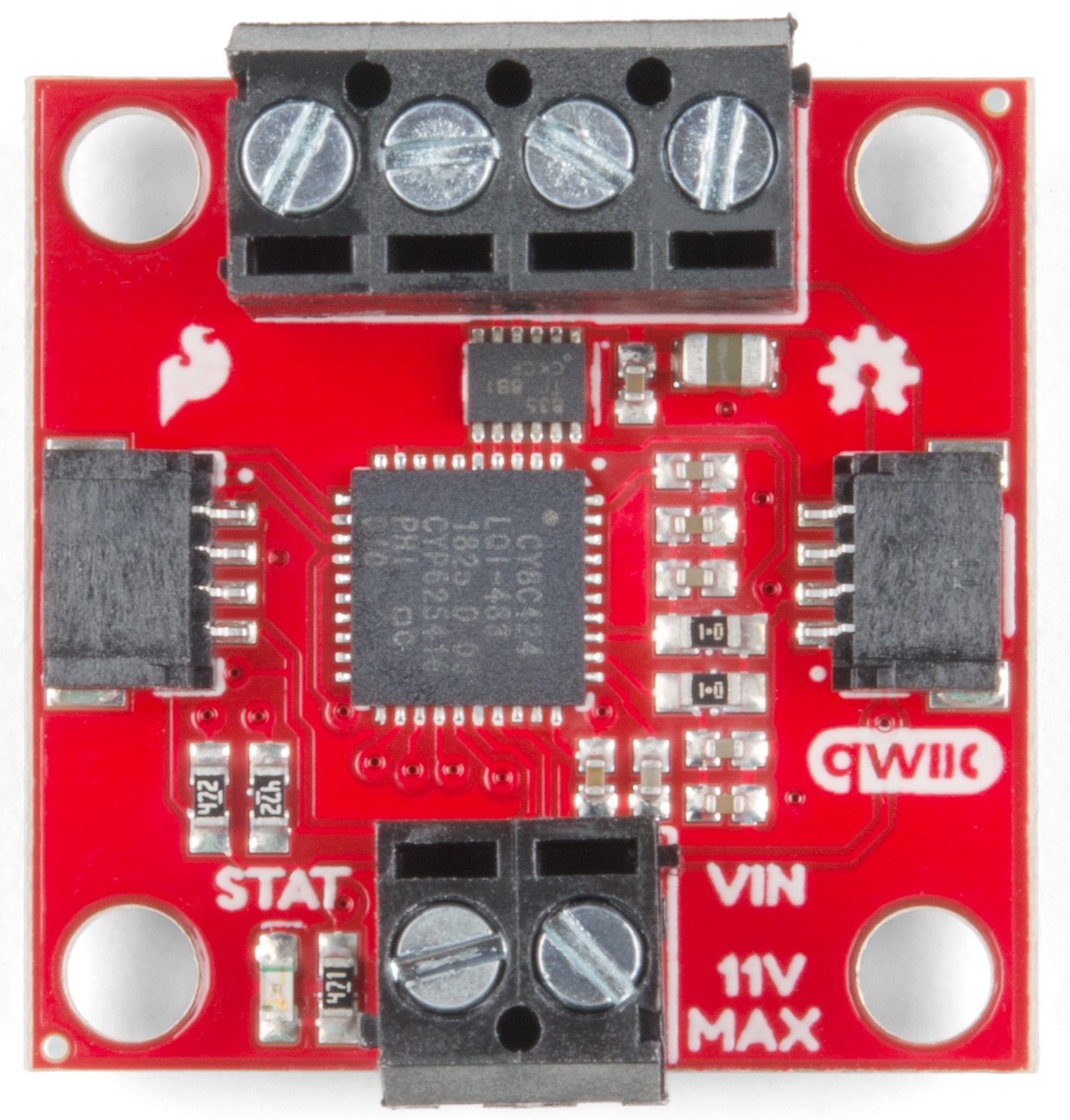
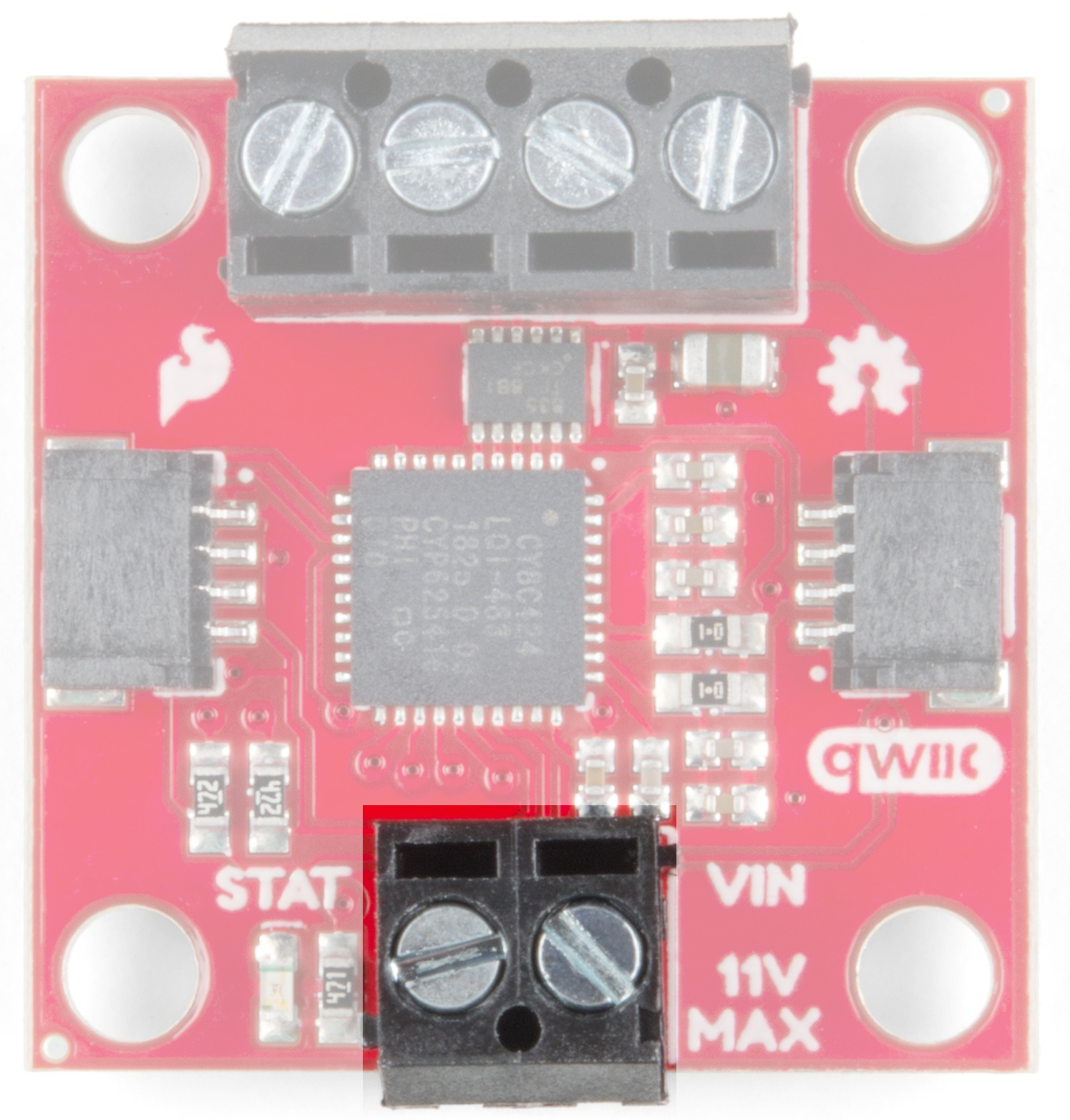
Controllable by I 2C or TTL UART signals Direction inversion on a per motor basis Global Drive enable Exposed small heat sink shape Several I2C addresses, default UART bauds available Power There are two separate power circuits on this board . Power for the motors is supplied through the VIN Connectors - you can provide anywhere from 3.3V to 11V to the "MAX 11V" and "GND" connections. Power for the PSOC and logic circuits is provided by the 3.3V inputs on the Qwiic connectors.
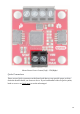
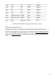
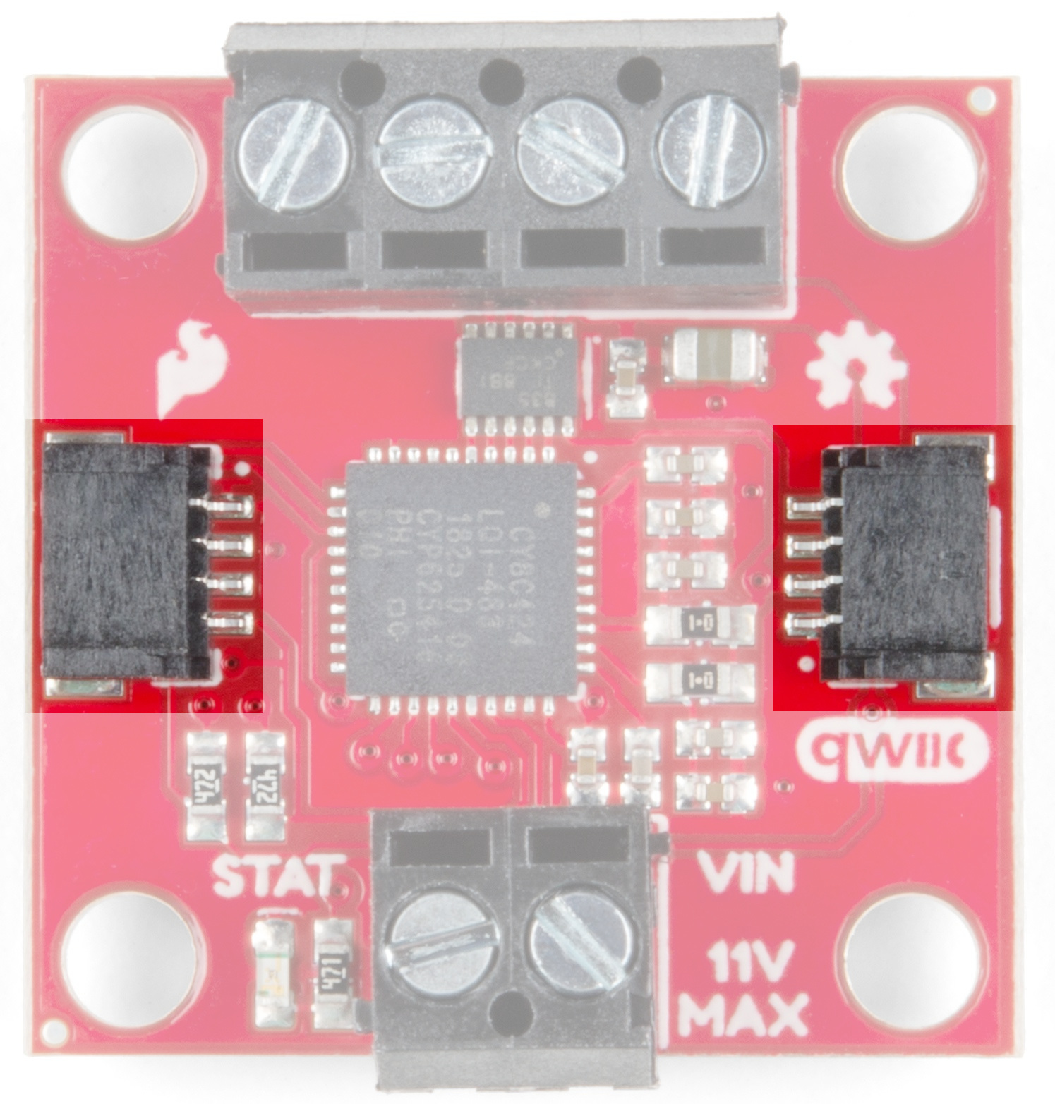
Motor Power Ports: Ground (Left) - VIN(Right) Qwiic Connectors There are two Qwiic connectors on the board such that you can provide power or daisychain the boards should you choose to do so.
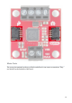
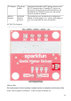
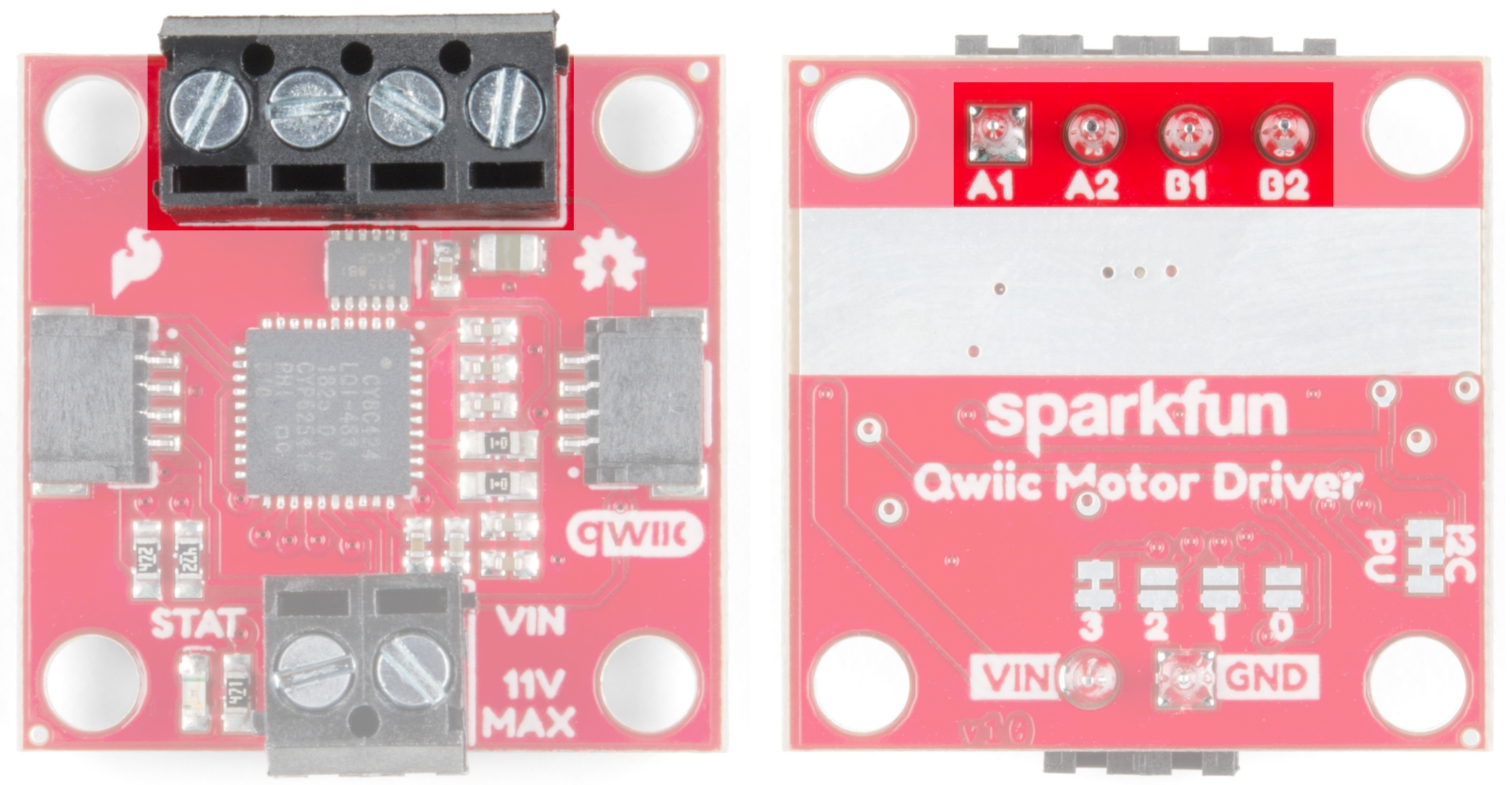
Motor Ports The screw pin terminals at the top of the board allow for two motor connections. They are labeled on the backside of the board.
From left to right on the front: B2-B1-A2-A1 Function / Connection Group Motor Port Description UART I2 C Name Direction A1 O Winding of first addressable location Motor A winding A2 O Winding of first addressable location Motor A winding B1 O Winding of second addressable location Motor B winding B2 O Winding of second addressable location Motor B winding Jumpers Jumper Usage Table There are 2 sets of jumpers to configure on this board.
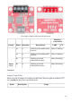
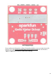
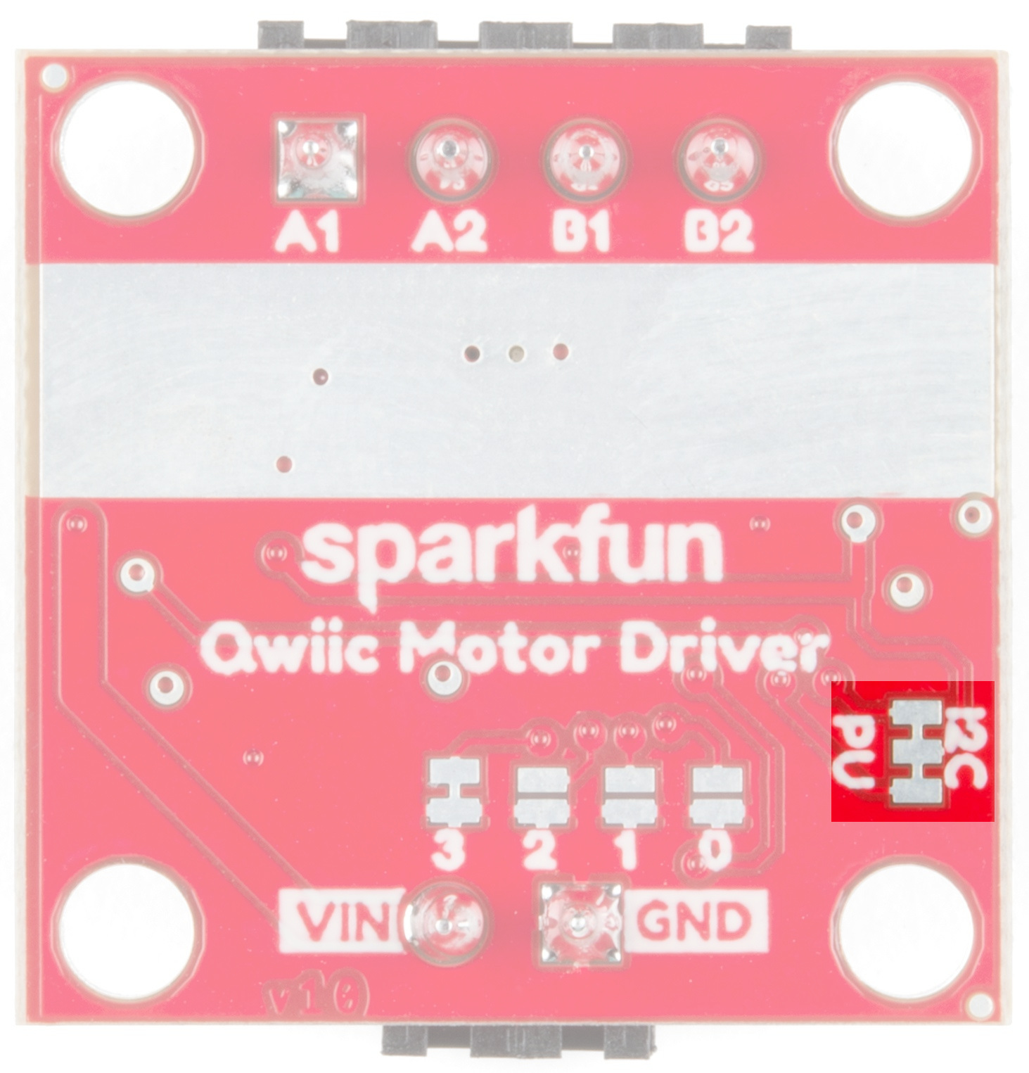
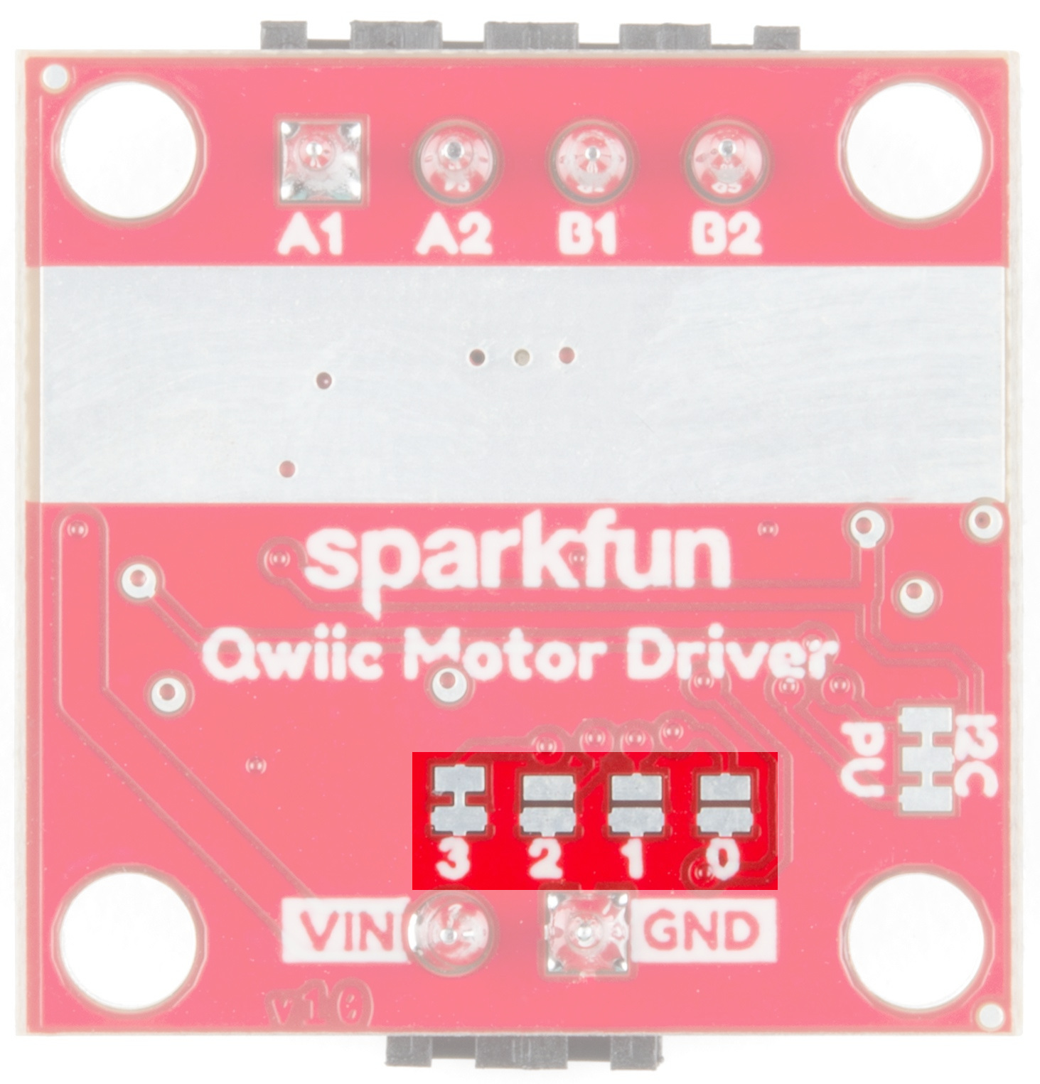
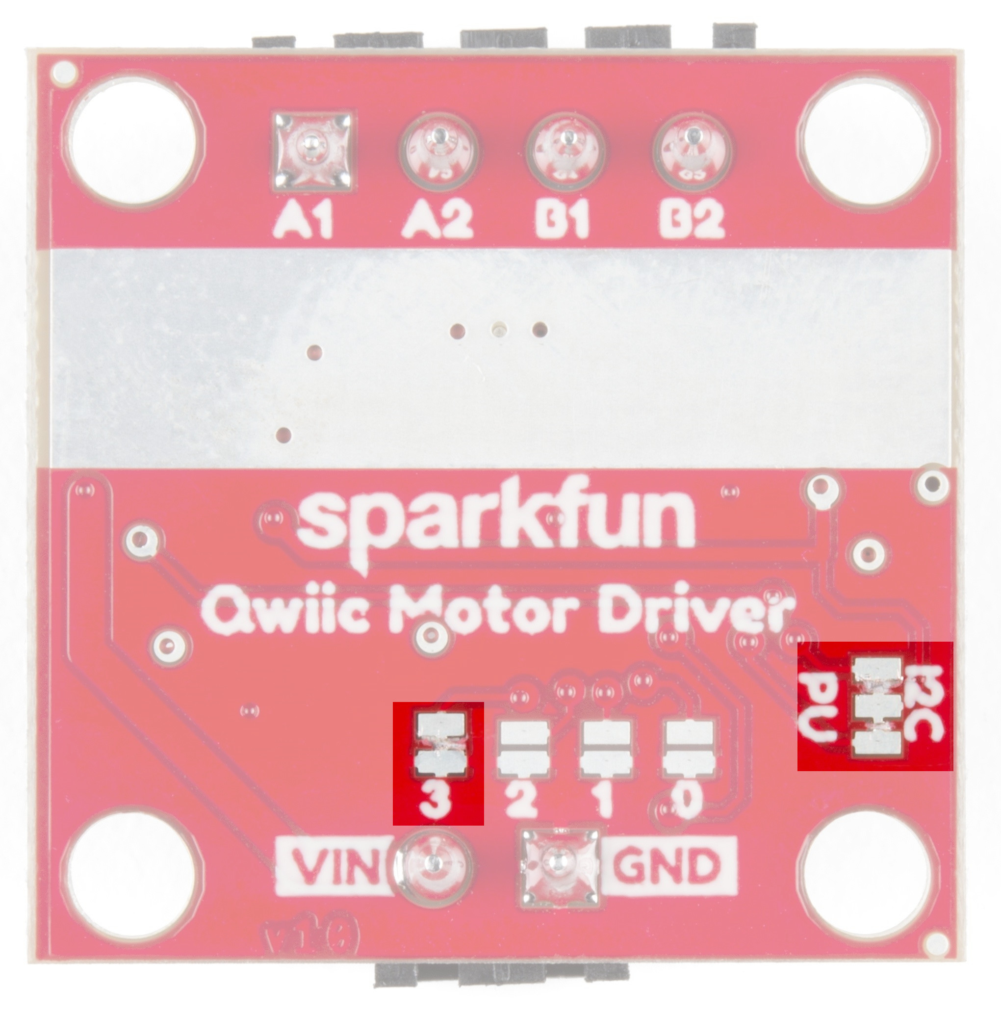
I2C Jumpers I2C pull-up enable Opening these disables theI 2C pull-up resistors used for I2C communication. If multiple I2C devices are being used, these pull-ups should be disabled on all but one device. If UART is being used, the pull-up resistors should be disabled. Address Jumpers Serial and function selection The config bits are 4 bits that form a configuration nybble. A closed jumper is a '1' and an open jumper is a '0'. See config table for more information.
Use this table to see what the user port, address, and expansion port will become in each configuration: Pattern Mode User Port User Address Expansion Port 0000 UART at 9600 UART N/A Master 0011 I2C I2C 0x58 Master 0100 I2C I2C 0x59 Master 0101 I2C I2C 0x5A Master 0110 I2C I2C 0x5B Master 0111 I2C I2C 0x5C Master 1000 I2 C I2 C 0x5D Master 7/18
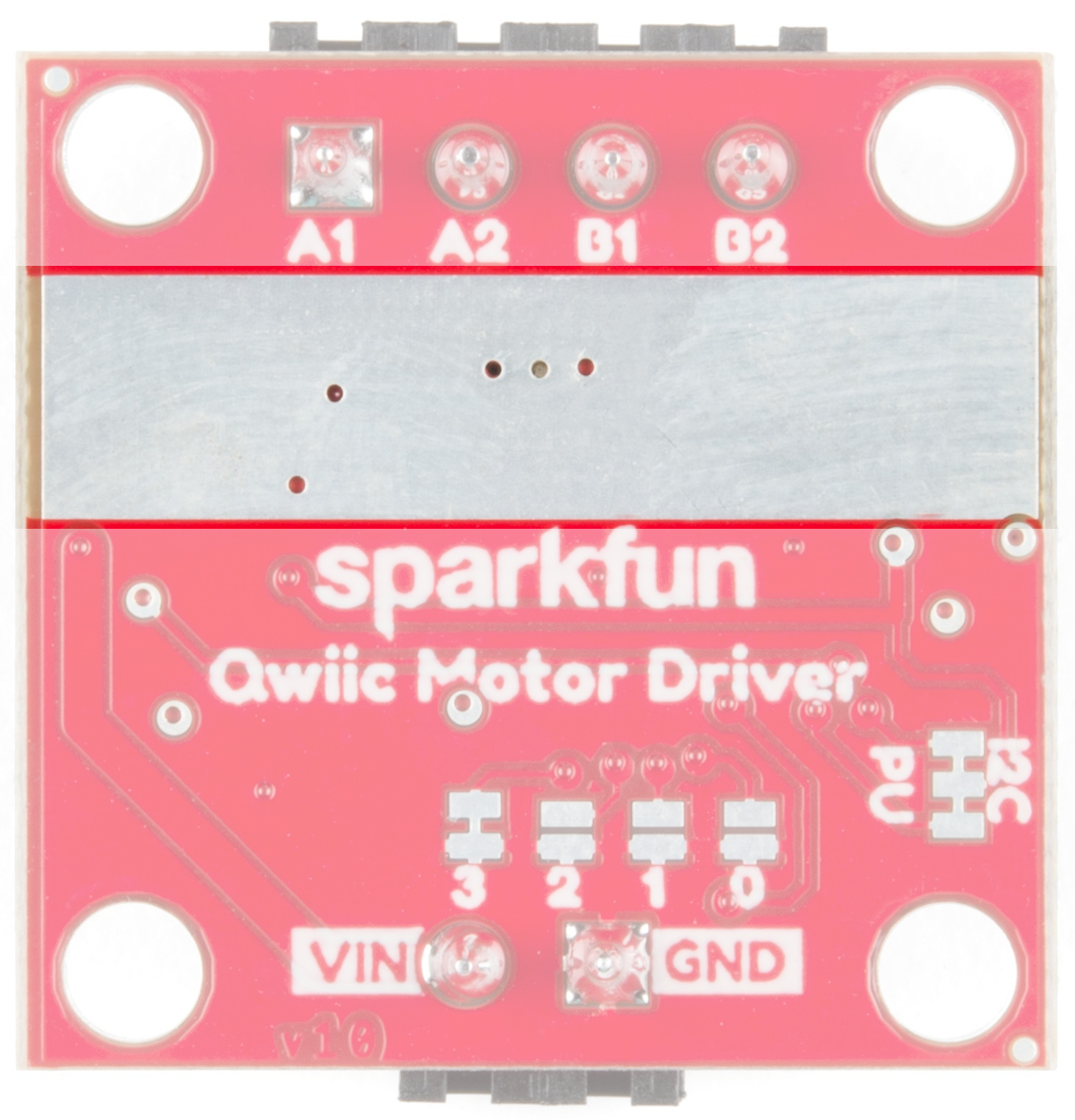
1001 I2C I2C 0x5E Master 1010 I2C I2C 0x5F Master 1011 I2C I2C 0x60 Master 1100 I2C I2C 0x61 Master 1101 UART at 57600 UART N/A Master 1110 UART at 115200 UART N/A Master 1111 N/A Reserved N/A N/A Bold text is the default setting for the Qwiic Motor Driver Thermal Conduction Area The Qwiic Motor Driver is designed to operate small robot drive motors without a heatsink; we were able to run up to about 1.1A continuous current without going above 100°C.
If you need more information on how to determine whether or not you need a heat sink, kick on over to the Serial Controlled Motor Driver Hookup Guide and scroll down to Typical Application Motors and Heat Sinking.
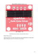
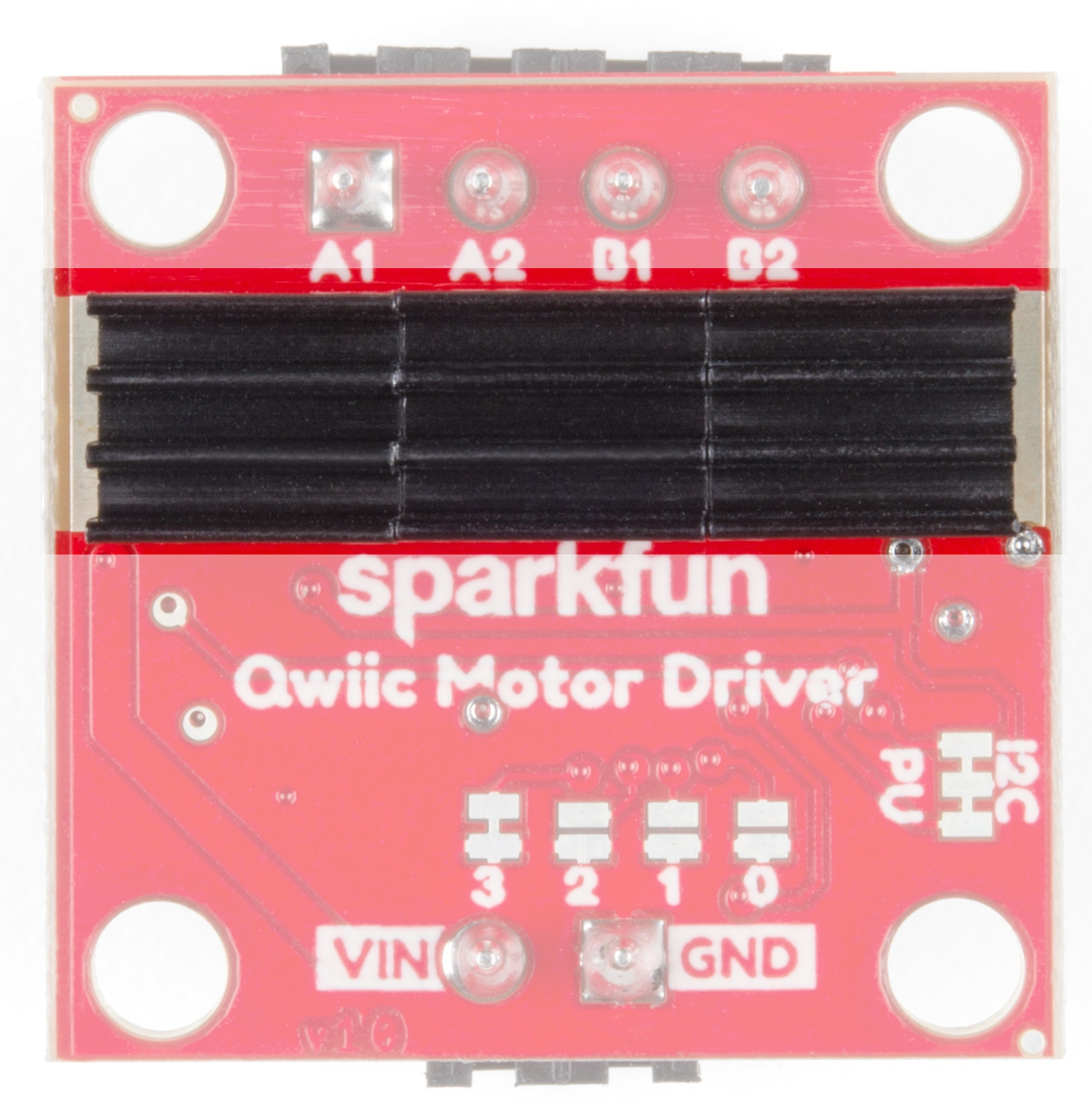
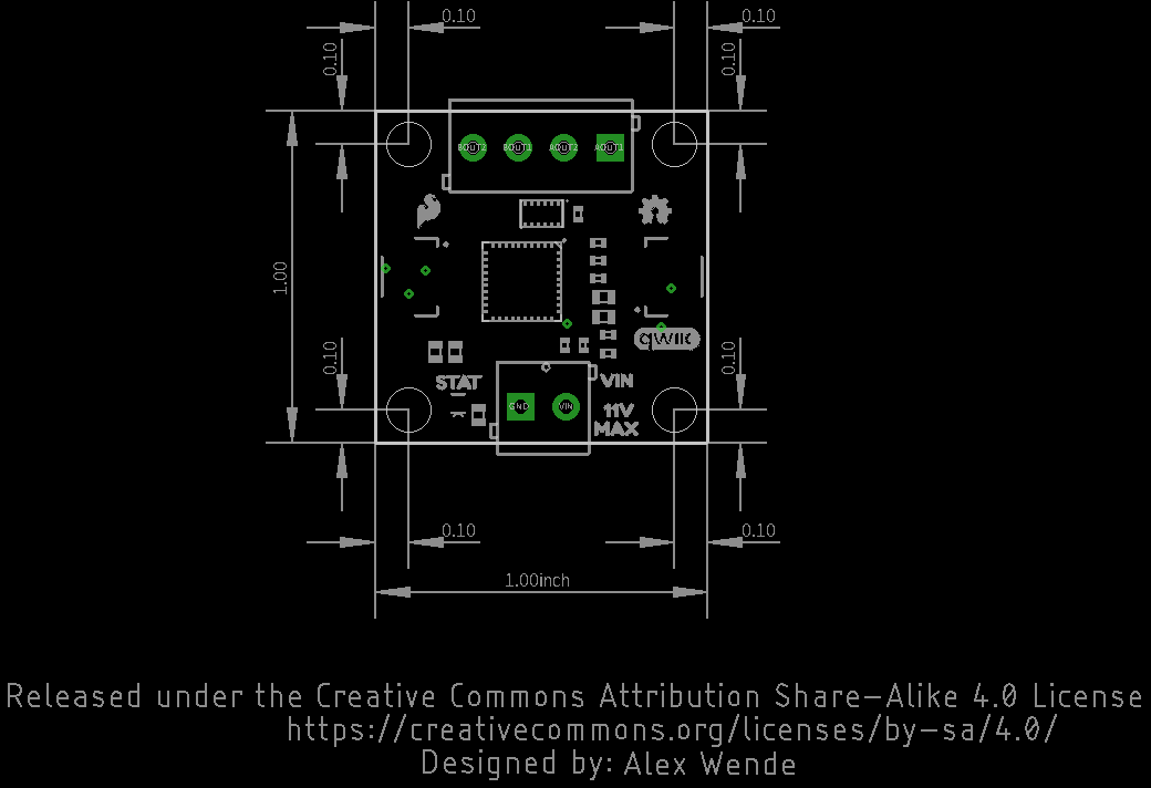
Small Heatsinks on the back of the Qwiic Motor Driver Board Dimensions All measurements are in inches. The Qwiic Motor Driver PCB measures 1x1 inch, with slight overhangs for the power and motor screw terminals.
Software Setup Note: This code/library has been written and tested on Arduino IDE version 1.8.5. Otherwise, make sure you are using the latest stable version of the Arduino IDE on your desktop. If this is your first time using Arduino, please review our tutorial on installing the Arduino IDE. If you have not previously installed an Arduino library, please check out our installation guide. A step-by-step guide to installing and testing the Arduino software on Windows, Mac, and Linux.
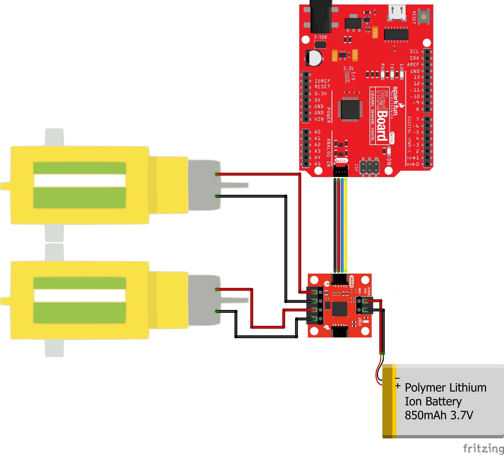
⚡ Note: In lieu of using the external LiPo battery, it is also possible to use the 5V and GND pins from the RedBoard Qwiic. Hardware Hookup Click the image for a closer look Testing the Motors The following test is essentially the TwoMotorRobot.ino example from the SCMD library, but with a few minor changes to account for the defaults of the Qwiic Motor Driver. Copy and paste the following code into your Arduino browser and upload.
SCMD myMotorDriver; void setup() { pinMode(8, INPUT_PULLUP); Serial.begin(9600); Serial.println("Starting sketch."); myMotorDriver.settings.commInterface = I2C_MODE; myMotorDriver.settings.I2CAddress = 0x5D; myMotorDriver.settings.chipSelectPin = 10; while ( myMotorDriver.begin() != 0xA9 ) { Serial.println( "ID mismatch, trying again" ); delay(500); } Serial.println( "ID matches 0xA9" ); Serial.print("Waiting for enumeration..."); while ( myMotorDriver.ready() == false ); Serial.println("Done.
void loop() { myMotorDriver.setDrive( LEFT_MOTOR, 0, 0); myMotorDriver.setDrive( RIGHT_MOTOR, 0, 0); while (digitalRead(8) == 0); for (int i = 0; i < 256; i++) { myMotorDriver.setDrive( LEFT_MOTOR, 0, i); myMotorDriver.setDrive( RIGHT_MOTOR, 0, 20 + (i / 2)); delay(5); } for (int i = 255; i >= 0; i--) { myMotorDriver.setDrive( LEFT_MOTOR, 0, i); myMotorDriver.setDrive( RIGHT_MOTOR, 0, 20 + (i / 2)); delay(5); } for (int i = 0; i < 256; i++) { myMotorDriver.
enable() is called to connect the drivers to the PWM generators. LEFT_MOTOR and RIGHT_MOTOR are defined to ease use of the setDrive( ... ) function. See the Arduino Library Reference section of the Serial Controlled Motor Driver Hookup Guide for more information on the functions defined in the Arduino library. Experiment 2: Interactive Commands with UART This example demonstrates the basic commands, plus some direct register access possible with only a UART available.
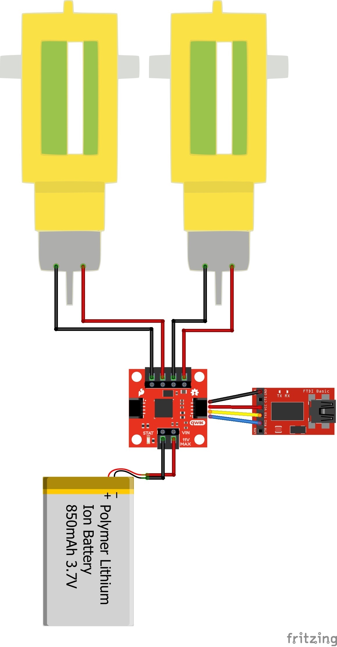
Make sure the Address Jumper 3 and I 2C Pullup Jumpers are cut as you see here. Connect the FTDI to the Qwiic Motor Driver as you see in the Fritzing diagram below. Attach two motors to the driver, one between A1 and A2, and the other between B1 and B2.
Click the image for a closer look Example Commands When you're ready, make sure you have the correct COM port selected in your Arduino IDE, open a Serial Monitor, and send the following commands: "R01" This will read the ID register and return 0xA9 "M0F50" This will tell motor 0 to drive at half speed, forward -- But nothing will happen yet! "E" This will enable all drivers. Motor 0 should begin spinning at half speed. "M1R100" This will tell motor 1 to drive at full speed in reverse.
search product forums and post questions.


