
User Manual


MPU-9250 Register Map and Descriptions
Document Number: RM-MPU-9250A-00
Revision: 1.4
Release Date: 9/9/2013
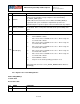
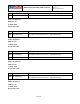
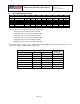
BIT
NAME
FUNCTION
[5]
DISABLE_XA
1 – X accelerometer is disabled
0 – X accelerometer is on
[4]
DISABLE_YA
1 – Y accelerometer is disabled
0 – Y accelerometer is on
[3]
DISABLE_ZA
1 – Z accelerometer is disabled
0 – Z accelerometer is on
[2]
DISABLE_XG
1 – X gyro is disabled
0 – X gyro is on
[1]
DISABLE_YG
1 – Y gyro is disabled
0 – Y gyro is on
[0]
DISABLE_ZG
1 – Z gyro is disabled
0 – Z gyro is on
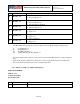
The MPU-9250 can be put into Accelerometer Only Low Power Mode using the following steps:
(i) Set CYCLE bit to 1
(ii) Set SLEEP bit to 0
(iii) Set TEMP_DIS bit to 1
(iv) Set DIS_XG, DIS_YG, DIS_ZG bits to 1
The bits mentioned in the steps (i) to (iii) can be found in Power Management 1 register (Register
107).
In this mode, the device will power off all devices except for the primary I
2
C interface, waking only
the accelerometer at fixed intervals to take a single measurement.
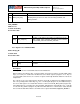
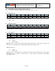
4.36 Register 114 and 115 – FIFO Count Registers
Name: FIFO_COUNTH
Address: 114
Serial IF: Read Only
Reset value: 0x00
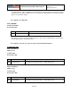
BIT
NAME
FUNCTION
[7:5]
Reserved
42 of 55