
User Manual

MPU-9250 Register Map and Descriptions
Document Number: RM-MPU-9250A-00
Revision: 1.4
Release Date: 9/9/2013
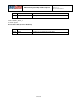
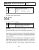
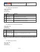
I2C_SLV3_DO
Serial IF: R/W
Reset value: 0x00
BIT
NAME
FUNCTION
[7:0]
I2C_SLV3_DO
Data out when slave 3 is set to write
For further information regarding Slave 2 control, please refer to Registers 46 to 48.
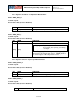
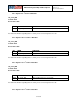
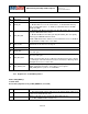
4.30 Register 103 – I
2
C Master Delay Control
I2C_MST_DELAY_CTRL
Serial IF: R/W
Reset value: 0x00
BIT
NAME
FUNCTION
[7]
DELAY_ES_SHADOW
Delays shadowing of external sensor data until all data is received
[6:5]
Reserved
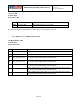
[4]
I2C_SLV4_DLY_EN
When enabled, slave 4 will only be accessed (1+I2C_MST_DLY) samples
as determined by SMPLRT_DIV and DLPF_CFG
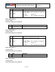
[3]
I2C_SLV3_DLY_EN
When enabled, slave 3 will only be accessed (1+I2C_MST_DLY) samples
as determined by SMPLRT_DIV and DLPF_CFG
[2]
I2C_SLV2_DLY_EN
When enabled, slave 2 will only be accessed 1+I2C_MST_DLY) samples
as determined by SMPLRT_DIV and DLPF_CFG
[1]
I2C_SLV1_DLY_EN
When enabled, slave 1 will only be accessed 1+I2C_MST_DLY) samples
as determined by SMPLRT_DIV and DLPF_CFG
[0]
I2C_SLV0_DLY_EN
When enabled, slave 0 will only be accessed 1+I2C_MST_DLY) samples
as determined by SMPLRT_DIV and DLPF_CFG
38 of 55