
User Manual

MPU-9250 Register Map and Descriptions
Document Number: RM-MPU-9250A-00
Revision: 1.4
Release Date: 9/9/2013
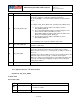
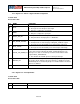
BIT
NAME
FUNCTION
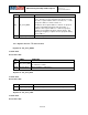
[4]
I2C_SLV2_GRP
External sensor data typically comes in as groups of two
bytes. This bit is used to determine if the groups are from
the slave’s register address 0 and 1, 2 and 3, etc.., or if the
groups are address 1 and 2, 3 and 4, etc..
0 indicates slave register addresses 0 and 1 are grouped
together (odd numbered register ends the group). 1
indicates slave register addresses 1 and 2 are grouped
together (even numbered register ends the group). This
allows byte swapping of registers that are grouped starting
at any address.
[3:0]
I2C_SLV2_LENG[3:0]
Number of bytes to be read from I2C slave 2
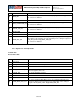
4.16 Registers 46 to 48 – I
2
C Slave 3 Control
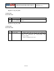
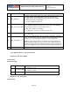
Register 46 - I2C_SLV3_ADDR
Serial IF: R/W
Reset value: 0x00
BIT
NAME
FUNCTION
[7]
I2C_SLV3_RNW
1 – Transfer is a read
0 – Transfer is a write
[6:0]
I2C_ID_3[6:0]
Physical address of I2C slave 3
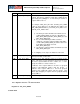
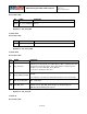
Register 47 - I2C_SLV3_REG
Serial IF: R/W
Reset value: 0x00
BIT
NAME
FUNCTION
[7:0]
I2C_SLV3_REG[7:0]
I2C slave 3 register address from where to begin data transfer
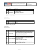
Register 48 - I2C_SLV3_CTRL
Serial IF: R/W
Reset value: 0x00
25 of 55